LS1 Drop Round 3

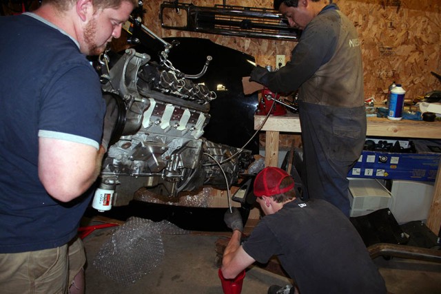
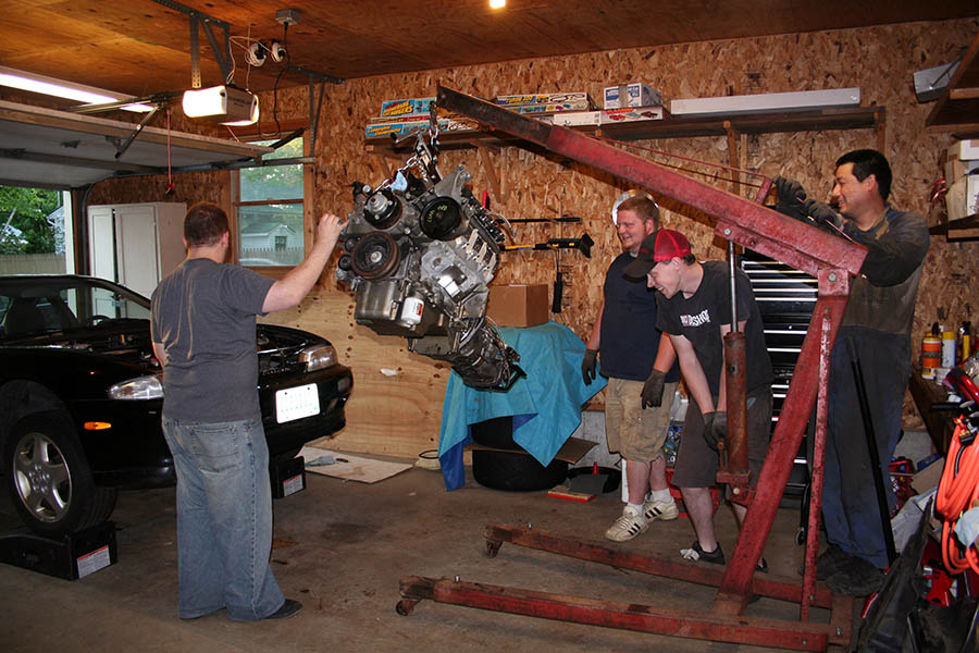
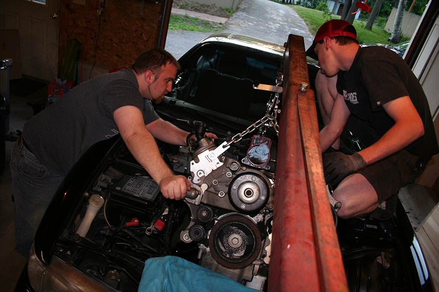
Ok so after waiting half a day for the mounts to arrive and having a little scare when they didn’t arrive with the mail I texted everyone I knew to come over and help me drop the motor in for hopefully one last time.

Before putting in the motor I was super jealous of how Randall’s tunnel looked and while the last time everything cleared I felt better with a little more breathing room. so we hammered out EVERYTHING forward of the pinch-weld up to the firewall and make it mostly smooth.

S14 Transmission Tunnel Hammered out for an LS1

Not as Nice as Randall’s job but after this  photo was taken I think we hammered it smooth a little more before sanding and painting it. Much better looking than it was before.

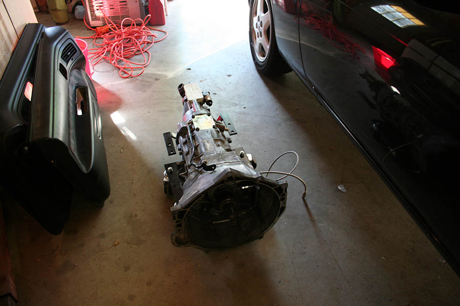
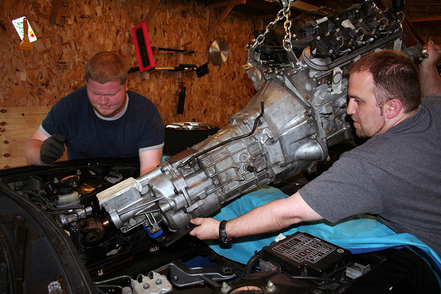
Also before dropping in the motor I checked the transmission cross-member. Previously the cross-member was too narrow such that if one side was bolted in it wouldn’t line up on the other. Also previously the cross-members were not square. This time the cross-member WAS square. it sat flush against the mounting surface and the bottom beam that held the transmission was level with the car. the mounting holes were still a hair off though. Previously the holes were off by about half a bolt width, now they were off by about a thread. We took a milling bit and widened the holes on one side just enough, and then repainted it.

Daft Innovation LS1/T56 Transmission Cross-Member with widened Bolt Holes

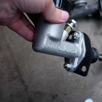
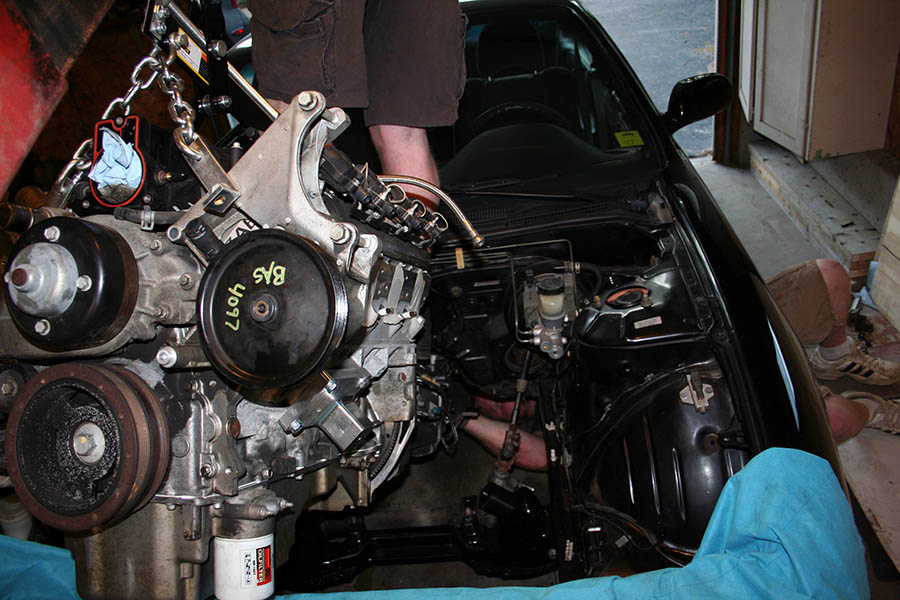
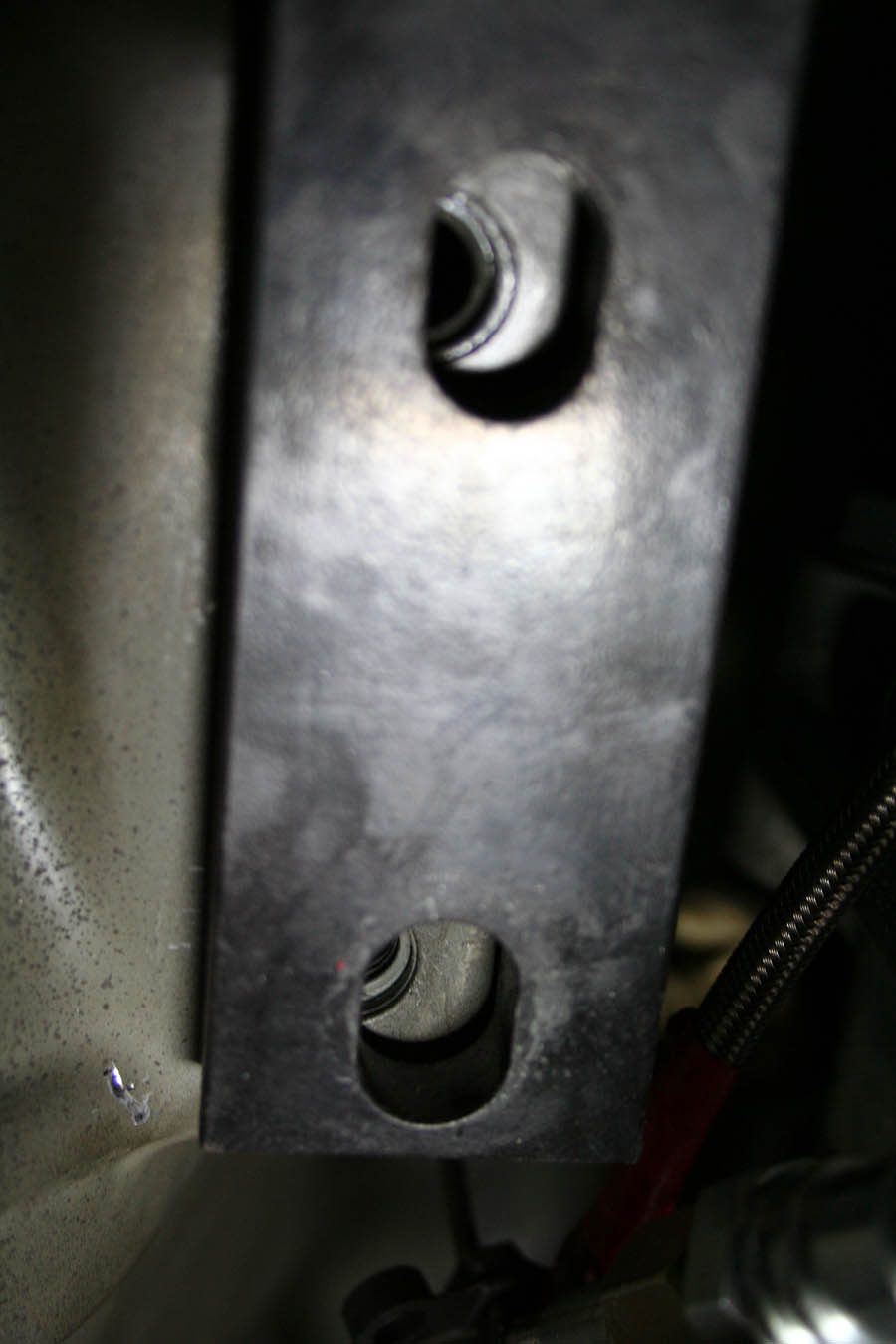
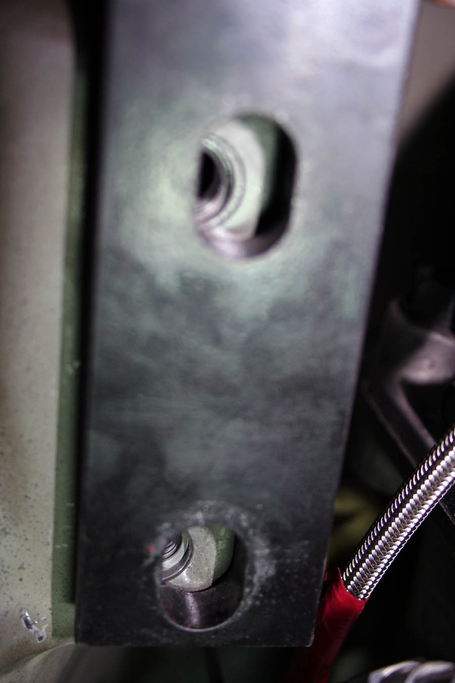
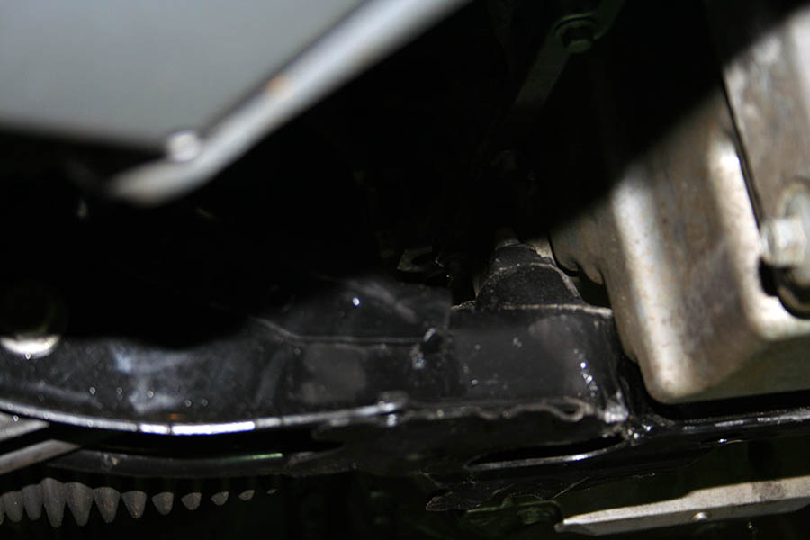
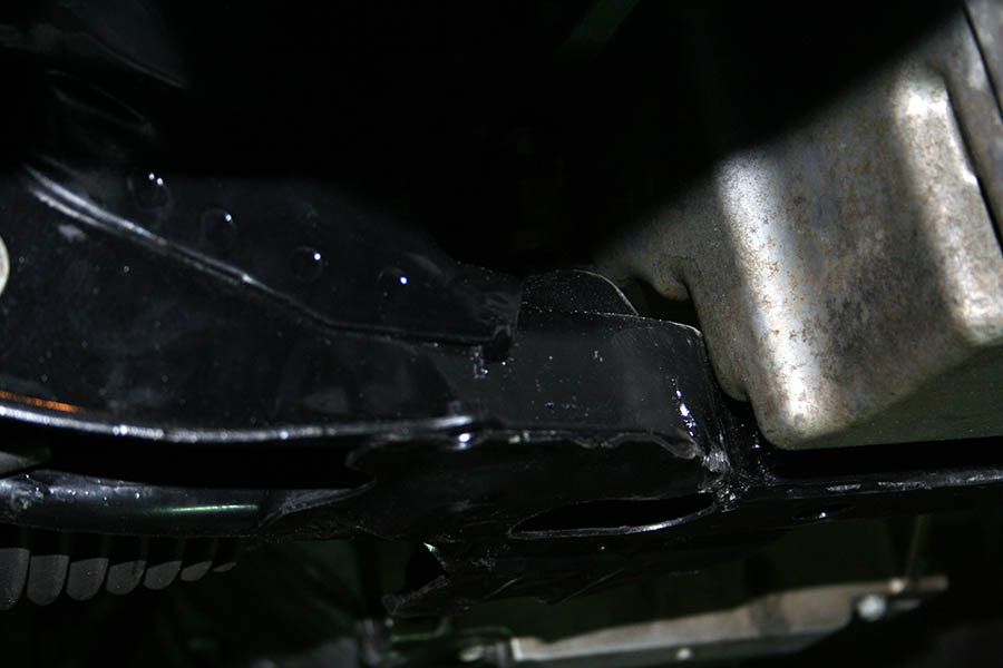
Also previously the threaded rods that go through the mount were exceptionally long. with the rod threaded all the way into the mount it stuck out the other side of the engine cross member quite a bit. Enough such that previously we couldn’t have the mounts attached to the engine when dropping it in as it wouldn’t slide into the cross-member.

Daft Innovations LS1 Mount bolt

Above you can see how much it stuck out after being bolted up to a cross member. I cut off 6 threads from the rod which made dropping the motor own with the mounts already attached much MUCH easier. In hindsight I probably could have cut off even MORE threads since the rod doesn’t technically need to be threaded all the way into the mount… that would allow me to screw it in a little while dropping the motor in, sliding the motor into the cross-member slots, then threading the rod out a little to put the nut on.

Twistedsymphony's S14 Corvette LS1 Daft Innovations Mount kit Twistedsymphony's S14 Corvette LS1 Daft Innovations Mount kit

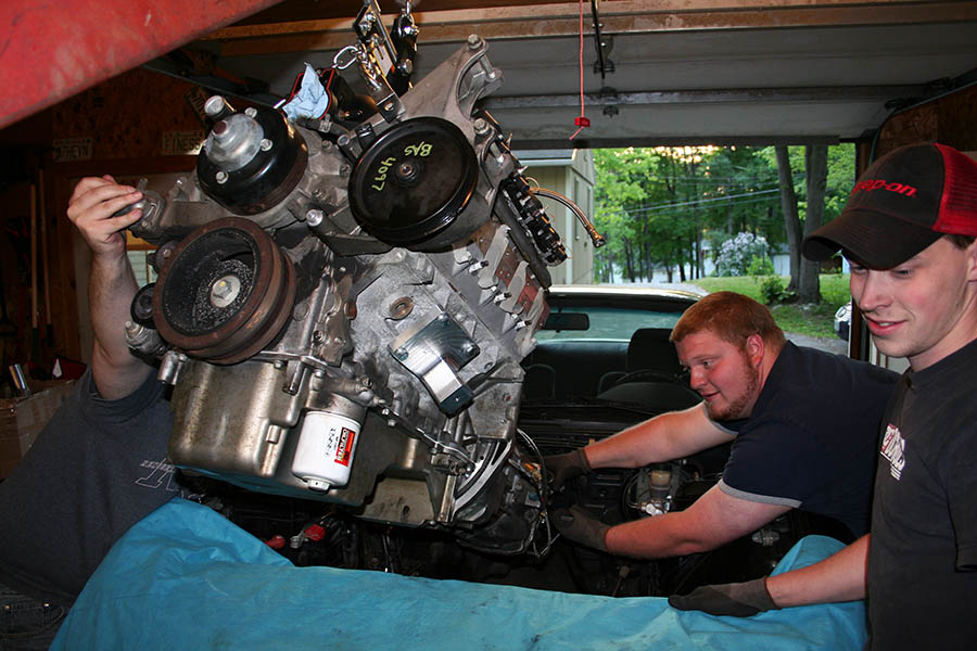
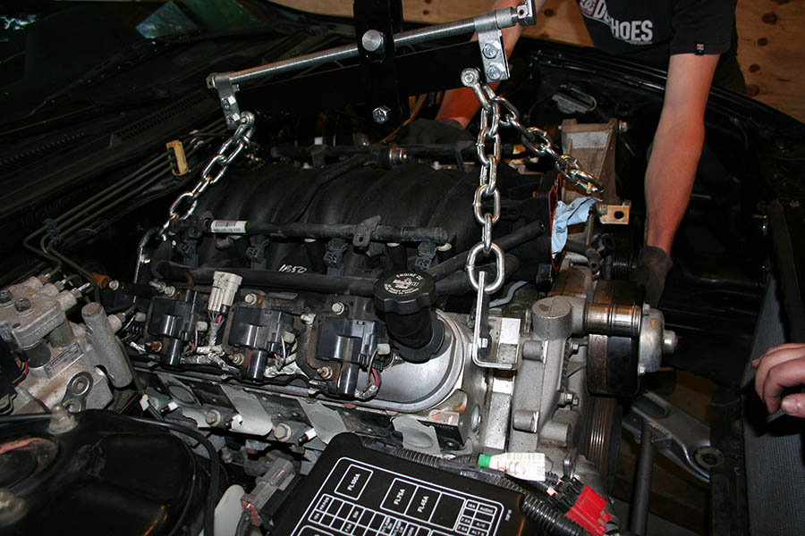
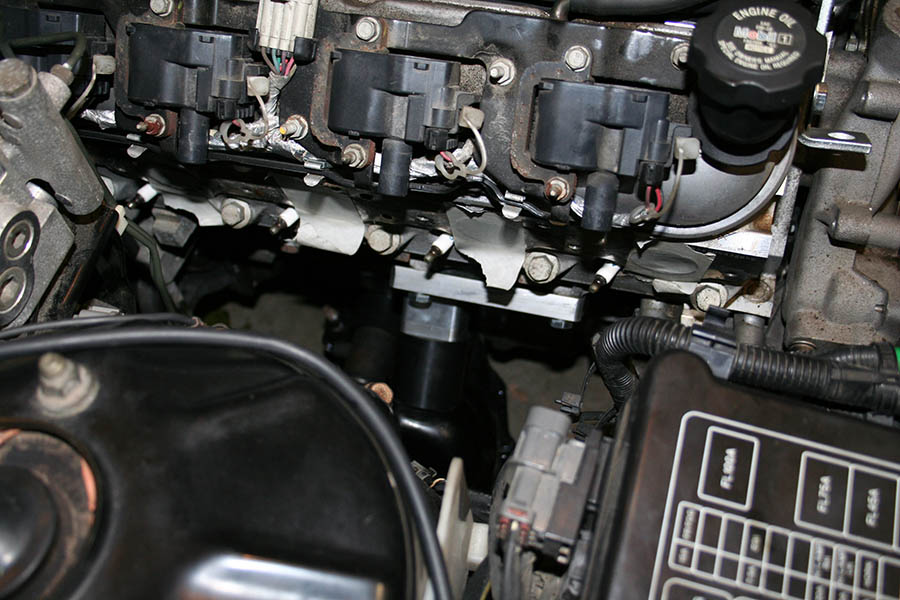
The engine now sits low and level like it should

We put some grease on the throttle body and the alternator and test fit the hood. The hood closed without issue and completely clears the throttle body. the top of the alternator bracket rubs just slightly but is nothing to be concerned about.

LS1 S14 Daft Innovations Alternator Hood Clearance LS1 S14 Daft Innovations Alternator Hood Clearance

The engine sits way lower now compared to how it did previously.

LS1 S14 Daft Innovations Alternator/throttle body Hood Clearance

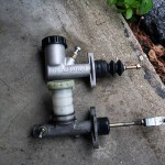
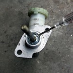
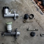
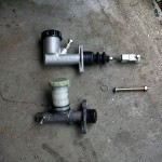
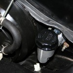
After fitting up the motor we tried for the headers. Drivers Side first, we hat to pull the coil packs, the alternator and the, searing column (Pro-tip: disconnect it at the bottom of the u-joint where it connects to the rack, and remove the pinch bolt completely), we also had to unbolt the master cylinder (the booster can stay where it is) and the header dropped right in no problem, with plenty of clearance around the rack and the frame rails

Daft Innovations LS1 S14 Header

The collector does actually come up a little bit in the back and rub against the floor though, I’m not sure what I’m going to do about that, I might see if I can shift around the motor a little (you’ll see why in moment) or failing that hammer the floor a little)

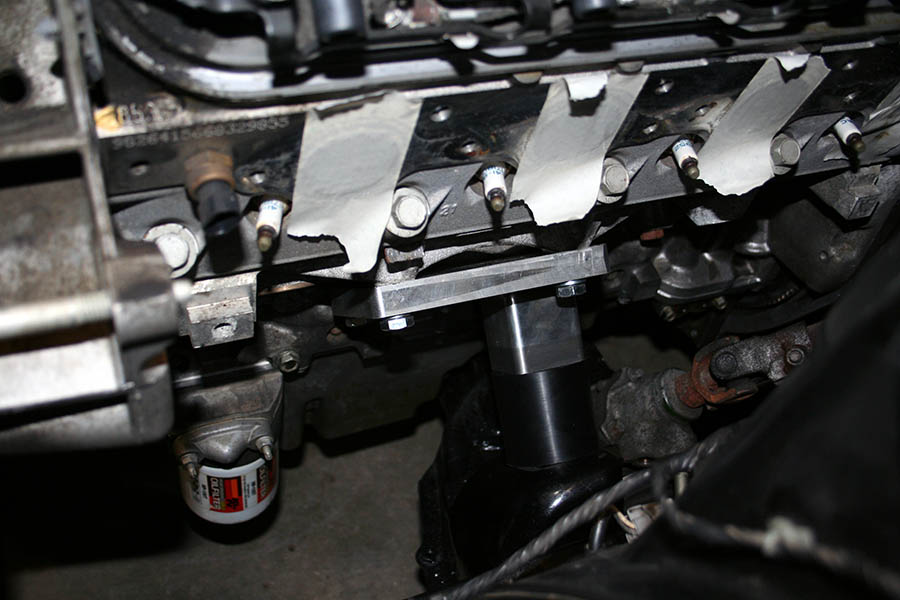
The passenger’s side header was a bitch to get in.  Again coil packs had to be removed, the starter motor had to be removed, also everything attached to the side of the fuse box had to be removed, the original S14 fuel filter and lines had to be removed and the huge bracket holding up the ABS module had to be removed too. we loosened the mount and hoisted the engine a little and the header went in after a little coaxing. Once it was in the clearance to the bell housing by where the starter goes is really tight but it clears, it also clears the floor unlike the driver’s side. however it hits the engine cross member.

Daft Innovations LS1 S14 Header Daft Innovations LS1 S14 Header Daft Innovations LS1 S14 Header

We marked it with a sharpie where it hits the cross-member. I’d like to see if I can shift the passenger’s side UP slightly and the driver’s side down slightly, that might fix this collision issue, as well as the floor board header collision on the drivers side, and clear up a tiny bit of space where the alternator bracket rubs the hood. Failing that I’m going to either hammer or slightly grind the top of the engine cross-member.

A note about the fitment of stuff, the ABS bracket will have to have the long arm that bolts to the frame rail removed completely, this shouldn’t effect it too badly since it bolts to the chassis in three other places. Also the two brakes lines that go directly down from the module (rear brakes, and front right brake) will need to be bent back a little since they rub on the header as it is. I will take pictures of these changes when I make them.

On a whole I’m very happy with how today worked out, a few tweaks here and there but this is about what I had expected the first time I attempted this. I appreciate that Rich made the effort to make this right and send me new parts that worked and got them here when I needed them.

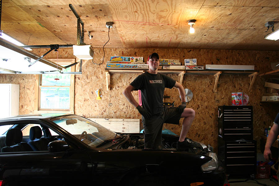
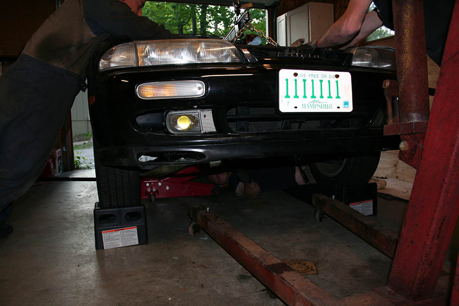
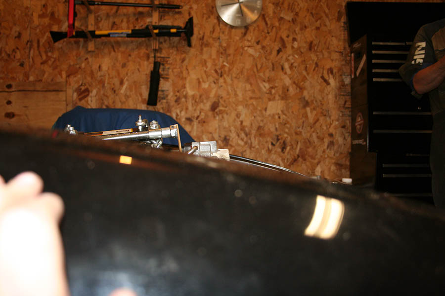
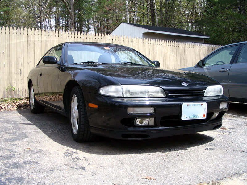
One last pic… I’m totally 4x4ing even with the LS1 in… and the car sat much lower with the KA.

S14 LS1

MT Parts

wooo… got my 5 speed brake pedal in today.

I must have found the only person on the planet doing an AUTO swap and he traded me all of my auto parts for all of his S15 5-speed parts… the only thing I still needed at this point was the brake pedal but the rest of it is handy to have around.

I spent time time bolting up the new brake pedal, and the swapping the push-rod on the master cylinder and bolting up the clutch pedal.

it’s small but it’s something

I took some pictures documenting how I prepped the Willwood CMC

Bitches in the Parking Lot…

I’m sure most of you have seen this video:

if you haven’t… well watch it now

I’m looking for someone who can make up some stickers for me on the cheap…

I had an idea and I was inspired…

This was the result after spending 15 minutes capturing the perfect still frame and playing around with photoshop for a while:

Bitches in the Parking Lot...

I would love to have a dozen or two of these as stickers.

Engine In

So Monday I finally got everything ready to drop the engine in: engine prepped, engine bay stripped, transmission tunnel hammered out, oil pan swapped, notched engine cross member installed, transmission installed on the engine,etc. The friends I had come over own a well respected local shop called [url=http://fujiispl.com/]Fujii SPL[/url], one of the guys we had here is from Japan and has at dozens of s-chassis engine swaps under his belt, at least 2 of them own swapped S13s.

engine bay cleared out

clutch lines installed and all unnecessary hardware removed

The torque wrench wasn’t working right so we had to use an old-school torque wrench to install the clutch hardware. Also the bolts for the the flywheel that I bought were the wrong size (and I somehow got 2 bags of those) we were also short 2 bell housing bolts… Aggravating. Thankfully the flywheel bolts from the original automatic flywheel worked on the new flywheel and we found some bolts that worked with the bell housing for the time being… placed those on the bottom so they can be swapped out later.

once the transmission was mounted up we set the clutch master in a vice and tested the lines for leaks… I didn’t want to have to pull the whole thing back out of the car to fix the lines if there was a problem. It was kind of ridiculous but it worked well and the lines held up beautifully

dropping in the engine:


Once the engine was in and we attempted to bold it up we ran into some major fitment issues. It’s sitting in the car right now but we’re going to have to pull it back out to figure out how to get everything to fit. We didn’t have time to test-fit the headers but a quick attempt showed that it wouldn’t be easy and I’m concerned about their fitment as well.

First thing we noticed was that the transmission cross member didn’t fit, we had major alignment issue with it but after we took out the mount and tried to bolt in the cross member alone (without it even touching the transmission) the bolt holes didn’t even line up… with the passenger side bolts lightly threaded in, this is what the driver’s side looked like:

The engine was IN and the mounts were bolted up and sitting flush the trans x-member was only bolted in on one side but sitting flush against the bottom of the car.

…but even still the engine sits slightly towards the passenger’s side, and it’s tilted slightly with the passenger’s side HIGHER than the driver’s side.

Checking the bottom we noticed that there seemed to be plenty of clearance of the driver’s side but the oil pan was actually rubbing on the x-member in 2 spots on the passenger’s side:

Also the hood clearance isn’t happening either: as you can see the hood wont even be close to clearing the throttle body, not to mention the engine is tilted with the front way higher than the rear, which I’m worried will cause issues with the drive shaft.

The alternator isn’t bolted on at the moment but it sits parallel with the throttle body and where it’s off to the side I would imagine there will be clearance issues with that also.

the S14 heater valve was removed before we put the engine in, but attempted to test fit showed that the engine is tilted far enough back that it passenger’s side rear coil pack will collide with the heater valve making it impossible to re-install. I’d considered trying to modify the system to use an in-cabin valve like the S13 but I’d rather not do that if I don’t have to, and there are plenty of people with S14s using the external valve (sikky’s kit even has you leave it on the firewall when doing the swap)

The Fujii SPL guys had some suggestions for modifying the kit for better fitment but if it came down to that I would rather have them fabricate completely custom mounts and not use the kit I bought at all.

It’s daft innovations “new” kit with CNC mounts, and a notched S14 cross member. the header I have are daft innovations as well (cnc bent) and I’m worried how they’ll fit.

I’ve sent an email to rich and hopefully he’ll get back to me soon so I can figure out what to do next.

We’ll likely be dropping the motor out the bottom next time which I’m hoping will allow us to install the headers off of the car and make everything go much more smoothly.

If anyone has any suggestions or advice, please let me know.

the only thing that went off without a hitch were the clutch and bleeder lines.. and I spec-ed out built those myself 🙄

Scooby Snacks

I saw this parked right next to the employee entrance at my work Friday afternoon.

Subaru Impreza 2.5 RS Supercharger

Subaru Impreza 2.5 RS Supercharger

I see this car daily, it’s owned by someone who works a my company, friday it apparently showed up with some extra power.

It’s a 2.5RS and I never paid it much mind since it got ding and dents all over it and it looks like it’s been through a few fender benders (which says to me it was owned by someone who just commuted it and didn’t care) kind of surprising to see this turn of events.

Large Format Scanner

I’ve been watching eBay for a while looking for a Large format scanner for a project I’ve been getting ready for and finally picked up this used Mustek A3 USB. It can scan up to 11×17. New these go for $175 shipped on eBay but I managed to grab this one for less than half of that.

I’m fairly pleased so far…

Mustek A3 USB

Oil Pan

More work got done over the weekend, Oil oil pan was pulled off.

crankshaft

GM apparently decided it was a good idea to rivet the gasket to the oil pan so those had to be drilled off.

rivit

Windage tray and the new oil pickup tube bolted right up

windage_tray

however now I’m stuck on this… this is the old dip-stick hole which needs to be plugged. On newer GM vehicles they tap it and use a 1/8 NPT pipe plug. Joe and I drove around to every store in Tilton and Lowes was the only place that sold the tap, no one sold the plug. so I ordered the plug off of ebay … after shipping I’m paying essentially $5 for a screw… waiting on that

dip-stick_hole

old cross member was pulled out too, here it is next to the new one. you can see the cut out center cross section and the engine mount humps are at a different angle (the new one is a modified RB cross member).

x-member

the new cross member is back in the car but the steering rack isn’t bolted back in yet, I decided to order some steering rack bushings while it’s off so I’m waiting for those.

I also got into today a bracket for the Clutch Master. This thing is f-ing slick… I don’t know why I’m so excited about this little part but I am. I guess I just think it’s cool that a custom part designed by some random guy looks so pro, and it was dirt cheap too, $25 shipped. I got it from Rigid over on silviav8.

cmc_bracket

I got my long-tube headers in too, I didn’t get a chance to snap any picture of them though…

LS1 and S14 Harness Integration

A minor update on the LS1 swap. I finished removing the LS1 engine harness as well as some other unnecessary stuff. I also got some new tools as well as a proper engine stand (though the motor isn’t up on it yet). The Fujii boys also stopped by briefly last weekend and pulled the starter motor, the Auto flywheel and the headders off… looks like a totally different motor now.

Corvette LS1 Corvette LS1

Next time I have a 2nd set of hands to help me I’ll throw it up on the stand (I don’t trust my ghetto-ass cherry picker to do it myself) then I can swap out the oil pan then drop it back down and throw on the new LS6 clutch… yummy

LS6 Clutch

I also spent some time pulling off a bunch of unneeded brackets and other crap from the transmission and cleaned it up a bit while I was at it and mocked up the new transmission cross member.

T-56 with Daft Innovations Transmission Mount and Crossmember

My main attention now will be on the harness, I dumped all of the harnesses that I need to tie together into a big box and brought it into my office… looks kind of overwhelming.

LS1 engine and tramssion Harness and S14 Engine Control Harness

Though spreading the KA harness out on the floor so you can see the whole thing all at once it doesn’t look so bad. Trimming off the KA bits will be the easy part… the hard part will be weeding through what is and isn’t needed on the LS1 harness.

Nissan 240sx S14 Engine Control Harness

Nissan 240sx S14 Engine Control Harness

Killer Bunnies Case

Years ago a good friend of mine turned me on to a great card game called Killer Bunnies. I instantly fell in love with the game and like most of my hobbies I decided to actively collect all the different expansions and rarities associated with it. The starter box holds a number of cards and Dice and had room to spare for 2 or 3 of the expansion packs. Past that I purchased 4 more expansions but never used them, simply because they wouldn’t fit in the box and carrying a whole stack of boxes around with you when visiting friends and family is rather cumbersome. Not to mention using the starter box you had to be creative when putting the game away to ensure that everything fit.

For months I looked for a reasonable case, poker cases were nice but they only held a small number of cards and the rest of the space was dedicated to chips, not easily modified either. Card cases for baseball collectors were either cheap cardboard boxes that held cards en-masse for storage or books where the cards were made be looked at rather then used. Even card holders for other games were almost always emblazoned with logos and artwork dedicated to that game (like Pokémon or Yugi-oh). I eventually found a company called Vanguard who makes cases for photo equipment. The cases are nice looking sturdy and contain half-cut foam cubes that you can remove to appropriately store your equipment. Most of the cases were too thin or small for what I needed but I finally found a case with a depth appropriate to fit cards, the Vanguard VGP-3202.

Killer Bunnies Case (Vanguard VGP-3202) Killer Bunnies Case (Vanguard VGP-3202)

Removing a few foam peaces you can easily create rectangular shapes just popping out foam with your hands. Each foam square is 1/2 inch by 1/2 inch and there are 2 depths, half way down the case and all the way down the case. (~2 3/4 inches total depth)

Killer Bunnies Case (Vanguard VGP-3202)

After determining the layout I wanted to use I removed all the appropriate foam pieces and did a test fit. I was careful to nail down the layout before I started and not break-off any foam that I didn’t intend to. I suppose I could have tried to glue some of it back on if I made a mistake but luckily that didn’t happen.

Killer Bunnies Case (Vanguard VGP-3202)

now that I have the cards in it would seem that the lid requires pressure to close completely. This would be find if I was using it to hold camera equipment but I’d rather not put pressure across the cards. They have a slight amount of pressure across them horizontally and that holds them in place, I would imagine vertical pressure from the uneven foam lid could potentially cause damage to the cards down the road.

Killer Bunnies Case (Vanguard VGP-3202)

Checking the depth of the lid’s foam with a needle there is more then enough space for the lid to close comfortably if I remove the foam. Carefully pulling the foam out and testing this proves correct. But now I have a different problem.

Killer Bunnies Case (Vanguard VGP-3202)

The glue used on the lid is some nasty stuff, breaking out my trusty Goo-Gone (never failed me in the past) only seemed to make it worse! After scrubbing at it for a half hour and wasting nearly a quarter bottle of goo-gone to no avail i decided it might be best to cover it up. The walls of the case are covered with a a thin foam material similar to what you might find in a crafts store. Off to Walmart down the street I picked up 2 sheets of foam for 48 cents a piece, even better the foam has a peel and stick backing, so I wont even have to break out the spray adhesive. While I was there I had the idea to affix an envelope to the lid to hold the manuals. Now that the original egg-carton foam has been removed there is ample head-room for the game manuals. So picked up some envelopes while I was there.

A single sheet of the foam covered the base of the lid perfectly covering up the bulk of the ugliness.

Killer Bunnies Case (Vanguard VGP-3202)

Unfortunately there was some glue spillage from the original foam on the walls as well so using a razor blade (and a scrap 2×4 as a backer to protect my desk) I cut some strips out of the second piece of foam and re-covered the inside walls of the lid

Killer Bunnies Case (Vanguard VGP-3202)

Once the lid was completely lined in fresh foam I put an envelope down for a test fit. I specifically went for a square flapped envelope as opposed to a triangle cut. I also have enough foam left over that I’ll be able to cover the envelope once it’s in palace.

Killer Bunnies Case (Vanguard VGP-3202)

I peel off the backing from the remaining foam sheet and center the envelop with the bottom aligned along once edge. I then cut off a bit of the envelope’s top so it’s the same size as the foam. The foam should hold it in palace once installed but to keep from accidentally putting the manuals BEHIND the envelope as opposed to IN the envelope I placed a thin strip of electrical tape along the back edge of the envelop that will create a smooth connection between the lid and the envelope making it easier to open the pocket and slide in papers.

Once that’s done the case is ready for use, and holds all the current decks as well as leaving space for the future installments

Killer Bunnies Case (Vanguard VGP-3202)

I’m very please with how the case turned out, it’s portable and durable and holds everything current and future which is exactly what I was looking for. Since it was originally intended as a camera case it has locks on the latches which is also very beneficial considering the card collection inside is easily worth over $100.

Marantz Fixed

After scratching my head over the broken Marantz I finally determined a cause of death.

Some friendly folks at diyaudio.com brought to my attention that the failure I experienced could have been caused if the speaker outputs were crossed, thus overloading the Darrington transistors.

Thinking back to the day it happened I had pulled out the receiver earlier in the day to hook up a Sega Saturn (which only produces stereo sound. eg: no center channel used) after playing that for a while the system was shut off. We returned hours later intending to play Xbox 360 (which is setup for surround sound. eg: center channel is used) and when the system was switched to the surround input by the harmony remote moments after being powered on is when it sparked an popped.

The crossed speaker wire theory fits because a few stray strands could have easily been grounded to the chassis or the other side of the speaker output when I pulled it out for use with the Saturn and then that channel wasn’t used until hours later when it popped.

Also there is no indication of any other component in the unit failing. Having 6 identical amplification circuits I was able to test  the dead circuit agains the working ones and aside from the part that blew everything checked out ok.

After researching parts I found that the transistor that blew is discontinued… replacing it would cost me $10 worth of parts + $8 shipping. that and I was a bit worried that maybe I was missing something and the next time I powered it up it would pop.

I decided to simply reconfigure the amp internally. Since it’s a 6.1 Receiver and I never use the Rear Center channel I basically just re-pinned the amp connector to use the rear center channel amp for the Front Center channel. then I removed a few other key component from the original Front Center Channel to ensure that it wouldn’t receiver power.

After putting it back together and testing it works great… just as it always has.

Since I’ve got a new receiver now I’ll be selling off the old one… I’ve got all of the original accessories, manual, even the original box it came in. I figure considering it’s age and what happened I’d probably let it go for $120 or so.

Marantz SR6200 Marantz SR6200 Marantz SR6200

I’m also going to get rid of the two Component Video/Optical switches I’ve got as well as the HDMI switch I’ve got and I’m thinking about selling off my PS1 and Gamecube as well since I don’t use either anymore.