Archive for the 'Hacks' Category

Page 3 of 4

Killer Bunnies Case

Years ago a good friend of mine turned me on to a great card game called Killer Bunnies. I instantly fell in love with the game and like most of my hobbies I decided to actively collect all the different expansions and rarities associated with it. The starter box holds a number of cards and Dice and had room to spare for 2 or 3 of the expansion packs. Past that I purchased 4 more expansions but never used them, simply because they wouldn’t fit in the box and carrying a whole stack of boxes around with you when visiting friends and family is rather cumbersome. Not to mention using the starter box you had to be creative when putting the game away to ensure that everything fit.

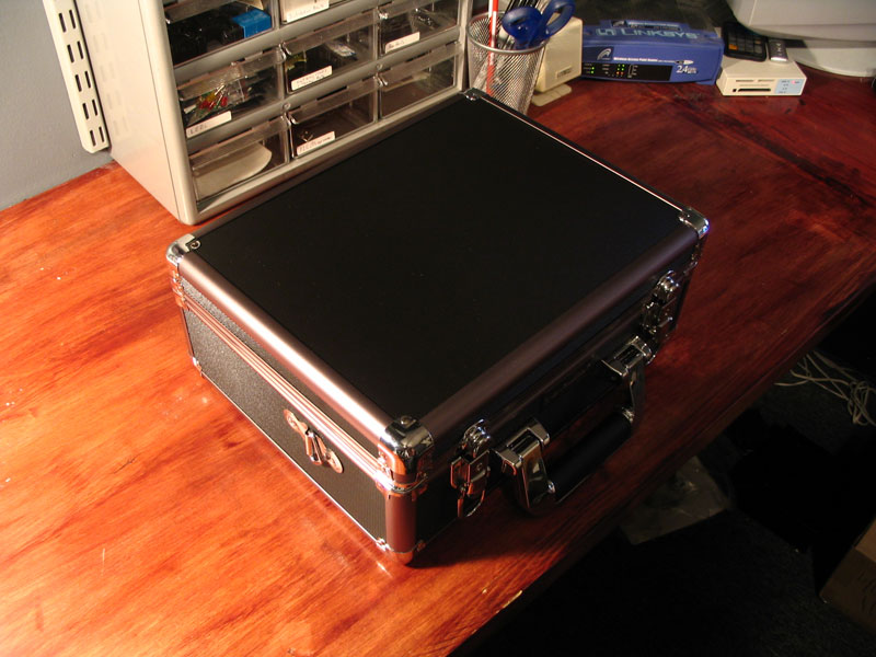
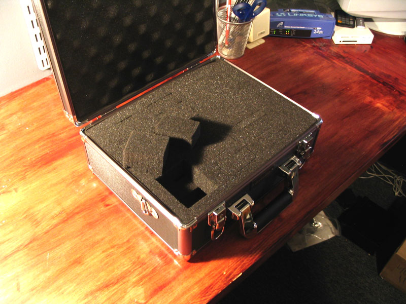
For months I looked for a reasonable case, poker cases were nice but they only held a small number of cards and the rest of the space was dedicated to chips, not easily modified either. Card cases for baseball collectors were either cheap cardboard boxes that held cards en-masse for storage or books where the cards were made be looked at rather then used. Even card holders for other games were almost always emblazoned with logos and artwork dedicated to that game (like Pokémon or Yugi-oh). I eventually found a company called Vanguard who makes cases for photo equipment. The cases are nice looking sturdy and contain half-cut foam cubes that you can remove to appropriately store your equipment. Most of the cases were too thin or small for what I needed but I finally found a case with a depth appropriate to fit cards, the Vanguard VGP-3202.

Killer Bunnies Case (Vanguard VGP-3202) Killer Bunnies Case (Vanguard VGP-3202)

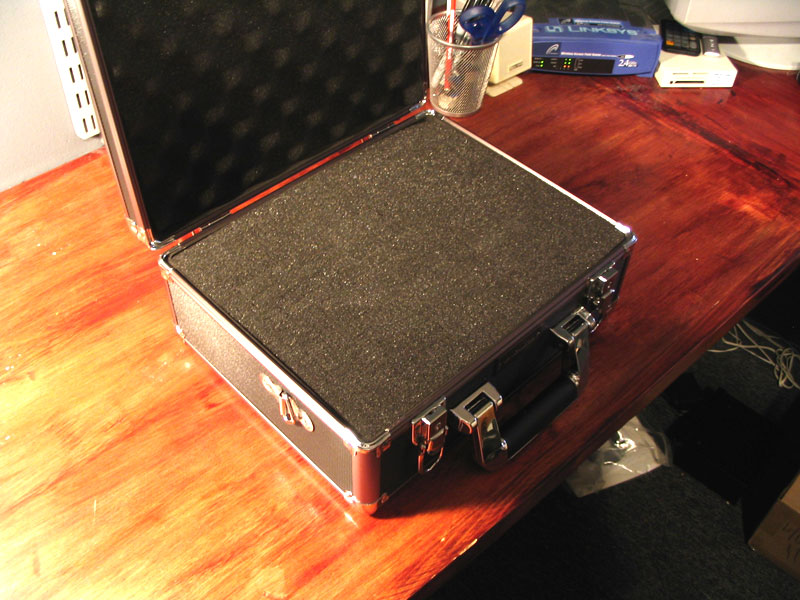
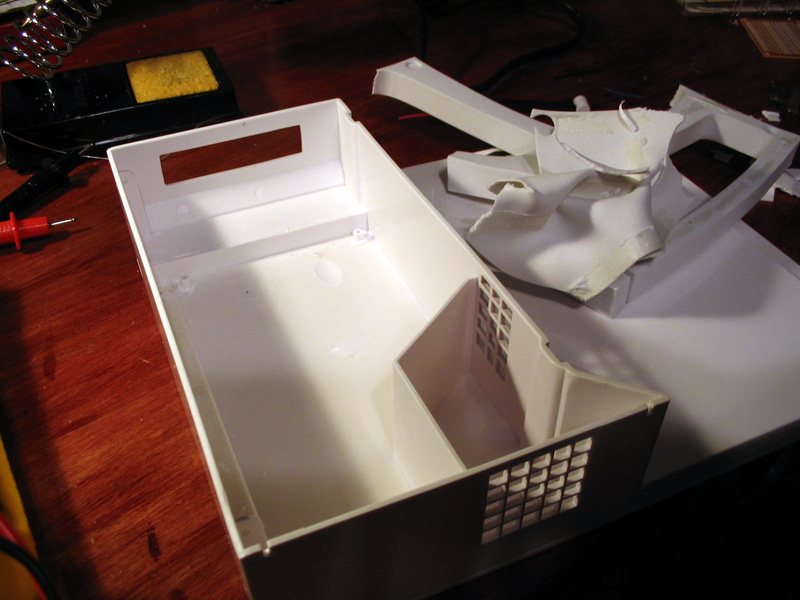
Removing a few foam peaces you can easily create rectangular shapes just popping out foam with your hands. Each foam square is 1/2 inch by 1/2 inch and there are 2 depths, half way down the case and all the way down the case. (~2 3/4 inches total depth)

Killer Bunnies Case (Vanguard VGP-3202)

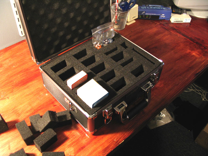
After determining the layout I wanted to use I removed all the appropriate foam pieces and did a test fit. I was careful to nail down the layout before I started and not break-off any foam that I didn’t intend to. I suppose I could have tried to glue some of it back on if I made a mistake but luckily that didn’t happen.

Killer Bunnies Case (Vanguard VGP-3202)

now that I have the cards in it would seem that the lid requires pressure to close completely. This would be find if I was using it to hold camera equipment but I’d rather not put pressure across the cards. They have a slight amount of pressure across them horizontally and that holds them in place, I would imagine vertical pressure from the uneven foam lid could potentially cause damage to the cards down the road.

Killer Bunnies Case (Vanguard VGP-3202)

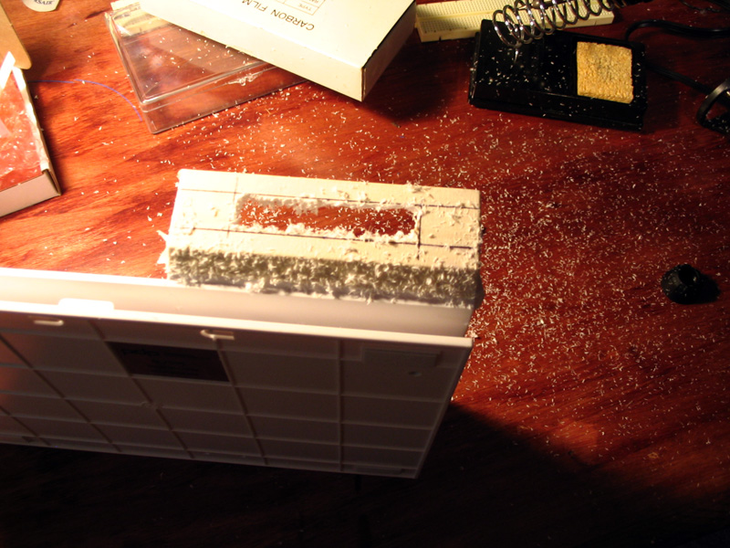
Checking the depth of the lid’s foam with a needle there is more then enough space for the lid to close comfortably if I remove the foam. Carefully pulling the foam out and testing this proves correct. But now I have a different problem.

Killer Bunnies Case (Vanguard VGP-3202)

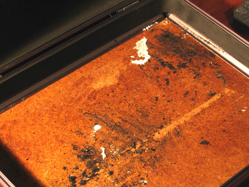
The glue used on the lid is some nasty stuff, breaking out my trusty Goo-Gone (never failed me in the past) only seemed to make it worse! After scrubbing at it for a half hour and wasting nearly a quarter bottle of goo-gone to no avail i decided it might be best to cover it up. The walls of the case are covered with a a thin foam material similar to what you might find in a crafts store. Off to Walmart down the street I picked up 2 sheets of foam for 48 cents a piece, even better the foam has a peel and stick backing, so I wont even have to break out the spray adhesive. While I was there I had the idea to affix an envelope to the lid to hold the manuals. Now that the original egg-carton foam has been removed there is ample head-room for the game manuals. So picked up some envelopes while I was there.

A single sheet of the foam covered the base of the lid perfectly covering up the bulk of the ugliness.

Killer Bunnies Case (Vanguard VGP-3202)

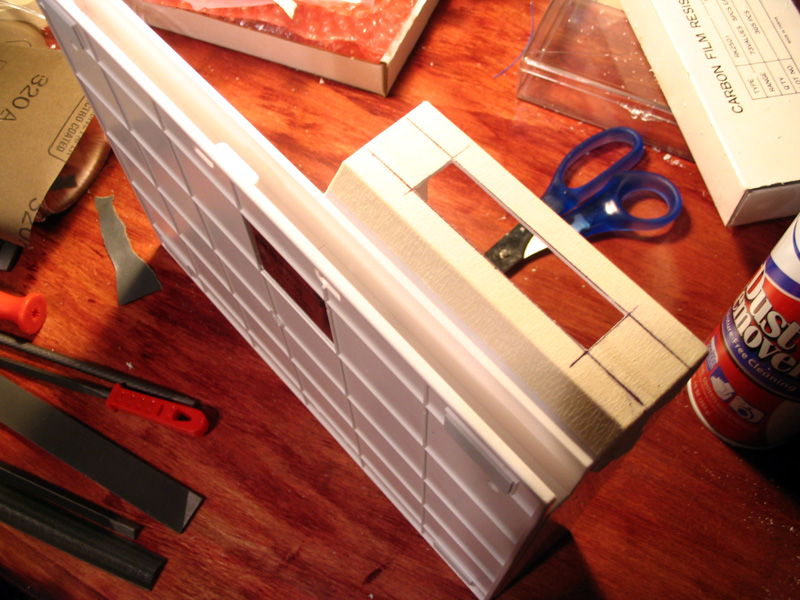
Unfortunately there was some glue spillage from the original foam on the walls as well so using a razor blade (and a scrap 2×4 as a backer to protect my desk) I cut some strips out of the second piece of foam and re-covered the inside walls of the lid

Killer Bunnies Case (Vanguard VGP-3202)

Once the lid was completely lined in fresh foam I put an envelope down for a test fit. I specifically went for a square flapped envelope as opposed to a triangle cut. I also have enough foam left over that I’ll be able to cover the envelope once it’s in palace.

Killer Bunnies Case (Vanguard VGP-3202)

I peel off the backing from the remaining foam sheet and center the envelop with the bottom aligned along once edge. I then cut off a bit of the envelope’s top so it’s the same size as the foam. The foam should hold it in palace once installed but to keep from accidentally putting the manuals BEHIND the envelope as opposed to IN the envelope I placed a thin strip of electrical tape along the back edge of the envelop that will create a smooth connection between the lid and the envelope making it easier to open the pocket and slide in papers.

Once that’s done the case is ready for use, and holds all the current decks as well as leaving space for the future installments

Killer Bunnies Case (Vanguard VGP-3202)

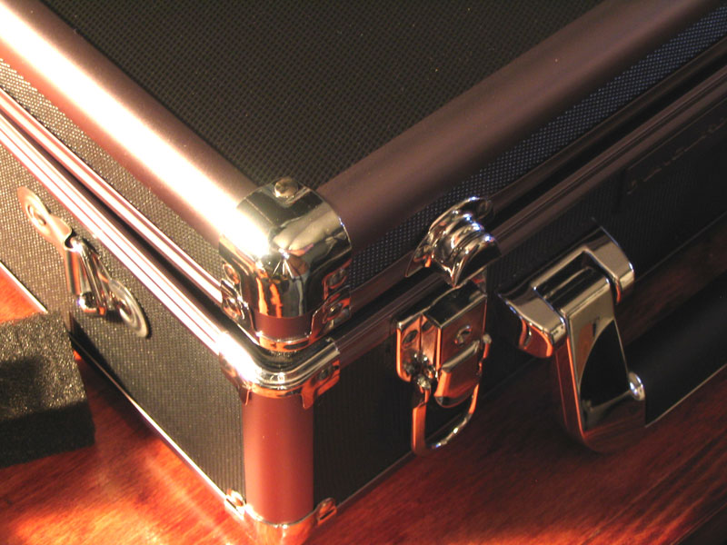
I’m very please with how the case turned out, it’s portable and durable and holds everything current and future which is exactly what I was looking for. Since it was originally intended as a camera case it has locks on the latches which is also very beneficial considering the card collection inside is easily worth over $100.

Out with the KA…

So Joe, Dan, and James stopped by tonight and pulled my KA.

Even taking their time, and taking frequent breaks to make fun of my lacking toolbox (I believe “even MacGyver had more to work with than this” was stated by Joe at some point) they still managed to get the thing out in about 2 hours time… I’ve even got ABS and AC and they managed to pull the motor leaving all of that equipment in place.

Quite impressive, and now the seal is broken so it’s time to start cleaning the engine bay and prepping the LS1…

KA24DE being removed from an S14 KA24DE being removed from an S14 KA24DE being removed from an S14

KA24DE being removed from an S14 KA24DE being removed from an S14 KA24DE being removed from an S14

KA24DE being removed from an S14 KA24DE being removed from an S14

KA24DE being removed from an S14 KA24DE being removed from an S14

Saturn to 360 Adapter Revival?

cracksolth left a few comments on the page for my Saturn to 360 adapter, as a result I started looking back into it. I contacted the guys from Acid mods (great guys BTW) to see if they were doing anything different that would help me streamline the design. In terms of communicating with the older “Matrix” style 360 controllers I didn’t really learn much that I hadn’t already discovered; however I did learn that the newer Common Ground style controllers are getting easier to find by the day and that most of the new colored controllers all use that style of innards.

They even supplied me with this handy graphic to determine the difference between a Matrix and a CG controller without having to crack it open.

Difference between Matrix and CG style controllers

As a result I’ve decided to abandon the Matrix style controllers for the time being and just track down a CG style controller to work with since that will allow me to dramatically reduce the pin count.

I’m going to do some playing around and if I like the results I might re-open this project…

My goals this time is to get it to a point of making a “kit” or perhaps even making it easy enough that I can lower the costs involved as well as the ease of install so that more people can get their hands on this. If this is something you’ve been waiting for then you’ve only got cracksolth to thank.

Shoot me an email or post a comment if you have ideas for features you’d like to see.

Door Handle Illumination Circuit

One of the members on Vehicross.info wanted a circuit that would light up the interior door handles of his car for a few seconds after he turned the key off to allow passengers to more easily find the door handles in the dark (they are actually difficult to find in the VX since they’re mounted quite low).

I came up with a circuit using a 555 timer in Monostable mode that looks for the ACC signal to dissappear, since it goes from 12V to float and since the 555 needs a pulse I used both a pull down resistor  to ground as well as an RC circuit to pull the 555 trigger back up.

 Door Handle Illumination Circuit

Power Folding Mirrors

I have a set of power folding mirrors for the 240, I’m thinking about customizing them so that they auto fold in and out with the ignition.

Here’s a circuit I drew up.

Circuit Diagram for Power Folding Mirrors

Amp Bypass Harness

To install my new speakers I had to build an Amp Bypass Harness for my 240sx

Amp Bypass Harness for my 240sx Amp Bypass Harness for my 240sx

Saturn to 360 Controller Adapter

May 1st I decided I wanted to tackle a big project. I wanted to do something that no one had attempted before and was beyond my current skill set. I had seen numerous inquiries on the forums from people who wanted to know how hard it was to use “X” controller with the Xbox 360. It always boggles my mind how little people know about this stuff and how 90% of the time they simply assume they can just cut the connector off of any cable, twist some wires together and call it a day. I wanted to do something to show everyone that these things were not impossible, nor were they that simple. I eventually decided to build an adapter that would allow me to use a Sega Saturn controller on the Xbox 360.

Saturn to 360 Adapter Logo

I chose the Saturn controller because the data protocol seemed simple and straight forward but complex enough that the circuit design would be interesting and challenging. I assumed that the converted output from the circuit would work easily with the Xbox 360 controller without any major problems, that turned out to not be the case.

I started off under the assumption that since the data from the Saturn controller was a simply multiplexed across four channels I could use some demultiplexers and get some good results. I didn’t know much about multiplexers/demultiplexer and as it turns out they don’t work the way I thought they did. So this didn’t work out.

Saturn Controller Protocol and PinoutSaturn Adapter First Test using demultiplexers

After the false start with the multiplexer I went back to the drawing board and started researching microcontrollers. I had limited experience with microcontrollers in the past but I knew enough that I knew it would work and that I would be able to figure out how to make it work. I eventually decided to go with a Microchip PIC solution using the PICkit2 and its included microcontroller. The first test was successful.

Saturn Adapter First Test with Microcontroller

After that I did a simple test to interface the microcontroller output to the Xbox 360 controller using transistors. This test was also a success. I had to actually use the guts of an Xbox 360 controller for communication between the console and the Saturn controller due to Microsoft’s security system. All major peripherals, especially the wireless ones have their communications encrypted and require a special chip sold only from Microsoft. This is also the reason no 3rd party wireless controllers have become available yet.

Once I scaled the transistor solution across all of the buttons I soon learned that the transistors would not work as anticipated. while my prior test had seemed to work, it had some side effects that were not immediately apparent.

Saturn to 360 adapter 1st Prototype with transistors

I rebuild the whole section of the circuit between the controller and the microcontroller and I ran a ribbon cable from the controller to the bread board just for my own piece of mind. This actually worked great but I was having the occasional voltage problems since the circuit was so large and drawing so much power. The power issues were worked out by simply adding more batteries.

Ribbon Cable Controller InterfaceSaturn to 360 Adapter Prototype 2a using Analog Switches

This ended up being the final version of the adapter. There were a few loose ends that I never tied up but I had met the goals that I had set out to achieve. I showed that controller adapters were possible albeit not easy either.

To my Surprise this project caught the attention of A LOT of gaming news organizations. The one I am most proud of however is an interview I had with Official Xbox Magazine in the UK. I got two whole pages dedicated to the interview and pictures as well as a teaser blurb on the front cover and main index. It has since been reposed on CVG sans pictures.

Here is a link list of all the other websites that covered it:

If you know of other news sites or corners of the web that ran an article or had some comments on it, let me know.

If you’re interested in the more technical side of the project the project log can be found on the Xbox-Scene forums. There is also a wrap-up post with all the important bits in one place. Another interesting bit is a fellow by the name of SaturnAR posted with some in-depth information on the Saturn analog controller which is well worth reading and he remains the only source of this info that I’ve ever seen.

Custom Easy Button

I’m sure nearly everyone is familiar with the Staple’s Easy Button from the commercials. Many of you are probably also aware that Staples actually sells Easy Buttons for $5 at their stores. It’s a simple device with batteries a speaker and of course a big button. Upon pushing the button you hear the “That was Easy…” catch phrase.

The Easy Button

I bought one to use at work since “easy” has come to be known as the ‘E’ word since certain people have come accustom to using the term to describe the difficulty of things that are decidedly NOT easy, at least that’s the reality that is usually discovered after far too little time has been dedicated to a particular project or task. Hence the button gets a push whenever anyone uses the term, or when something is completed successfully that actually did end up being easy.

While it’s entertaining, the gag can get old. For a brief period of time I was moved into the engineering area which sees a lot more traffic and my Easy Button saw it’s fair share of pushes as people found it funny to press as they walked on by chuckling to themselves as if they had just perfectly executed a joke. It didn’t bother me but it was clear that a few others who sat near by were weary of hearing “That was easy” continuously throughout the day… I decided that, for the benefit of myself and those who sat within ear shot, I needed to get some revenge.

I decided that since the Easy button was really just a button attached to some circuits I could very easily just make it a button attached to some different circuits; more specifically a circuit that could play custom messages instead of a pre-recorded one.

I went to radio shack because I remember them selling little voice recorder circuits in the past. I didn’t find one of those but I did find a key fob device that featured a voice memo function among other things. I decided it was small enough that I could strip off all the other crap that I didn’t need and shrink it even further if need be.

[I regret not taking any pictures of the key fob device pre-hack]

I started by pulling apart the Easy Button to see if it had the necessary space I would need to make it work. As it turns out there is a large piece of metal inside the button used to prove it with the satisfying CLICK when pushed. Also inside were two pieces of metal rod to give the button weight. I decided to do what i could to keep these features intact so that the button would not loose it’s quality. Thankfully the area under the metal plate was empty space albeit tight when taking into account that the plate needed to flex when the button was depressed. I also decided to keep the speaker since it was much larger than the one included with the key fob recorder.

Once I pulled the key fob device apart probed for the appropriate points I needed for microphone, speaker output, play and record buttons, as well as the points for the batteries. I pulled off all of the unnecessary stuff and got the circuit down to a really small size. Before attempting to fit everything into the Easy Button case I first made sure that the circuit worked.

Easy Button Circuit Test

Once I ensured that the circuit worked the way I intended I mounted the voice recorder circuit into the empty space below the metal “click” plate and ran wires. Since the metal plate would likely rub against the circuit I put some electrical tape over it to provide isolation from shorts.

Easy Button Voice Recorder Install Easy Button Voice Recorder Covered

Next I put the metal plate back in place and screwed down the original Easy Button circuit which was modified to short out all of it’s components except for the actual button, which was now connected to the voice recorder.

Easy Button Modified Circuit

Since I was using a different circuit that was designed to run on different batteries at a different voltage I decided it would be best to make the Easy Button fit the circular batteries as opposed to building additional circuitry to adapt AAAs. Also the battery holder portion of the button provided ample room to mount my microphone and record button as well. I started by modify half of the battery compartment to fit the circular batteries by bending and cutting some of the original battery hardware.

Easy Button Modified Battery Door

I then modified the other half of the battery door to fit the microphone and record button, both of which I got from my spare parts box. I then put it all back together and had an easy button that looked and felt just like the original but now could be programmed to say whatever I wanted.

Easy Button Record Button, Mic, and New Battery holder Easy Button hacked and ready

To get back at my co-workers I recorded the phrase “Ha Ha! Not this time. Get back to work.” and proceeded to get a good chuckle at every unsuspecting person who walked by pushed the button and then turned around for a double take when they realized that the button was heckling them rather than responding with the soothing Staples advertisement.

Wii LCD

Ever since I saw the WiiFree LCD mod I’ve been racking my brain how to integrate an LCD into such a small case and the key to it all came to me one weekend, after which I went straight online and ordered everything I needed.

I originally wanted to use a RED 20×2 I had laying around but it wouldn’t fit how I wanted it. I have a 16×2 green VFD I could have used but it would require some tinted glass so I didn’t want to use that. I ordered two White on blue 16×2 LCDs from CrystalFontz which will mesh perfectly with the Wii’s natural styling.

I had been racking my brain trying to figure out how to fit an LCD into the Wii’s case because of how incredibly small it is and how tight the innards are. While I was poking around Circuit City I saw an interesting product, a horizontal stand for the Wii with a matching box off to the site designed to hold a remote and nunchuck. As you can see from these pictures the potential for a slick LCD add-on is great.

Wii LCD Case Unmodified Wii LCD Case Inside Unmodified

I started by measuring my LCD to get the dimensions of the viewable area, and playing with placement to make sure that it would fit inside the case with the lid closed and still look centered on the outside. Even with all the empty space here the height of the case and the angled bottom still made this a tight fit that required a little bit of trimming. Once I got the placement down I masked off where I was going to cut my window. Used a rotary tool to rough cut it and then used metal files to make the cuts clean and flat and then finally some light sanding on the edges to make them look natural and slightly rounded. I did it this way because I didn’t want to have to paint the case the glossy plastic of the stand matched the Wii perfectly and having to paint or bondo to cover up any mistakes would have ruined that perfect match.

Wii LCD Case Masked off Cutting Area Wii LCD Case Rough Cut Wii LCD Case Cuts Filed Flat

Once the cuts were made I gutted the interior to remove all of the crap that I don’t need. While I don’t need the empty space either I figure that it might be beneficial for future projects, it might be cool to hardwire a set of Wavebird wireless adapters in here or hardwire a USB port and a LAN adapter or something along those lines. There’s certainly enough space for all of those things.


Wii LCD Case Gutted

Now that the case was done I could turn to the electronics. I knew that I needed a small PCB and I wanted it to sit like a backpack on the back of the LCD. I wanted to mount the chip to the back of the LCD rather than inside the Wii because if I ever need to reflash it getting at the chip would be trivial. Using pin headers to connect everything meant that I could easily pull the system apart for repairs or adding features down the road. I started by laying out how the electronics would all fit on a PCB, then I soldered them in place, then I went pin by pin from the WiiFree install instructions to make sure all of the points on the chip lined up with all of the points on my custom pin header. It was a lot easier than it looks. One benefit to using a socket for the chip is that you can solder it in place with the chip removed, meaning you don’t risk damaging the chip with the heat of the iron.

Wii LCD Case Electronics Laid out Wii LCD Case Electronics Completed

Once I had the electronics all soldered up I could place the LCD inside the case to complete the look. The LCD was simply hot glued in place. Using multiple dots of hot glue is the best procedure as even if one drop breaks the whole glue seam wont rip off like a string. Hot glue is fine for situations like this too because it’s not really holding any weight or resisting any force. Not to mention if you screw up it’s pretty easy to remove it and fix it.

Wii LCD Case Complete

So I have this awesome looking Wii LCD case now. I went ahead and soldered up a ribbon cable internally to a pin header hanging out the back of the case (sorry I forgot to take pictures) and I was all ready to get this thing up and running. Unfortunately when I went to flash the firmware to my chip I came to the painful realization that by USB programmer, a programmer that I bought because it works with 99.9% of Microchip’s PIC products did not support the chip I was using. I would seem that this is one of the very few chips that falls into that .1% range. So without the firmware I had to go back to using my internal 12F629 for the time being. I’ll get around to building a programmer for the chip I’m using to get the LCD up and running but it will have to wait until the next time I put in my big annual Digikey parts order.

You can follow the progress of this project using the project log on Nintendo-Scene.

Xbox LED Ring

Back when I was involved with hardmods.net, “rb” and I considered opening up shop and making a few kits to sell. There were a number of factors why it never happened but we actually designed and prototyped an LED ring for the Xbox 1. At the time there weren’t any LED rings on the market really. People who had LED Rings were basically making their own by hot gluing LEDs to the inside of their case. The effect was pretty cool, I actually had one setup with 16 blue LEDs at one point and another one setup with eight red LEDs in an “X” pattern. I snapped some pictures of the two setups in use with some custom laser engraved jewels from Xport, though the pictures really speak more for the quality of the jewels than they do for the LED ring.

Halo BlueFace BlueBlack Hole Blue

Halo RedFace RedBlack Hole Red

The Hardmods LED ring was basically just a PCB that you would solder to yourself. What was interesting about our design is that you could set it up to to have anywhere from 1 to 16 LEDs mounted evenly around the ring. I’ve still got 3 prototypes sitting on the desk in my office.

Hardmods.net LED Ring Prototypes Hardmods.net LED Ring Prototypes

I don’t have the schematics though. (rb, if you’re reading this send it to me please!) When I got the prototypes I also received a poster sized print of the LED ring layout with color coded traces. It had no dimensions but it’s the only documentation I ever had for the things. I’m not sure exactly where it is but I’m sure I could find it if I looked. It’d be no more useful than if I simply scanned one of my prototypes anyway.