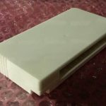
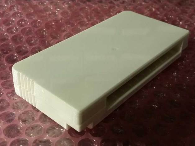
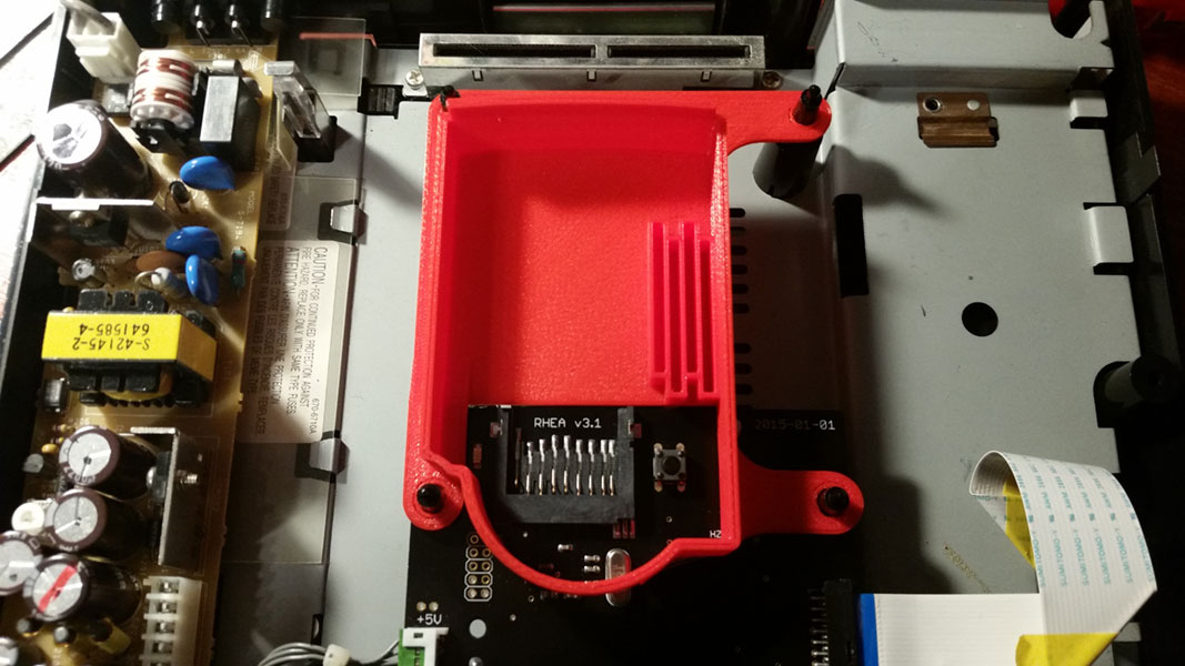
This is a replacement cartridge housing for Security carts used on Capcom System 3 (aka CPS3) arcade hardware. This is the hardware used for Street Fighter III and a few other Capcom games from that era. What prompted this housing creation was that the Security carts on the CPS3 are prone to failure, they have a backup battery that once dead will kill the rest of the cart with it. Darksoft developed a “Super Bios” that allows you to remove the battery and use a single cart with any game for the system. And later he developed a reproduction cartridge to replace any that may have been thrown out once they died. Since these reproduction carts have no housings I designed one that could be used to hopefully spare any original cartridge housings from being stolen for this purpose.
There are essentially 3 configurations of the files here each with a unique purpose.
The standard front and back housing are designed to be used with reproduction security cartridges or modified “Super Bios” cartridges that do not have a battery. Since the reproduction cartridges don’t have a housing to go with them hopefully this 3D printed housing will serve as a useful alternative to stealing one from an original cartridge.
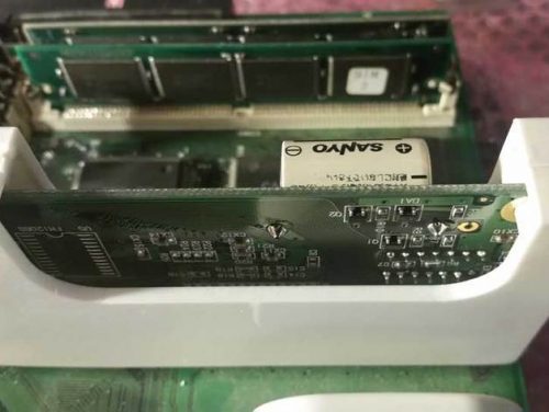
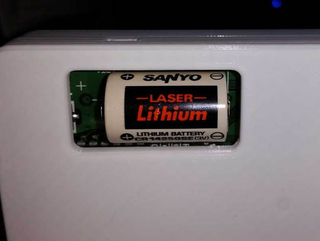
The back housing with a “Battery window” includes a cut out designed to accommodate the large battery that sticks out the back of an original, un-modifed security cart. the window is elongated to the left to accommodate a larger replacement battery that may use the larger foot-print solder points. this also allows you to easily see the production month/year of the battery for easily determining when a replacement might be needed.
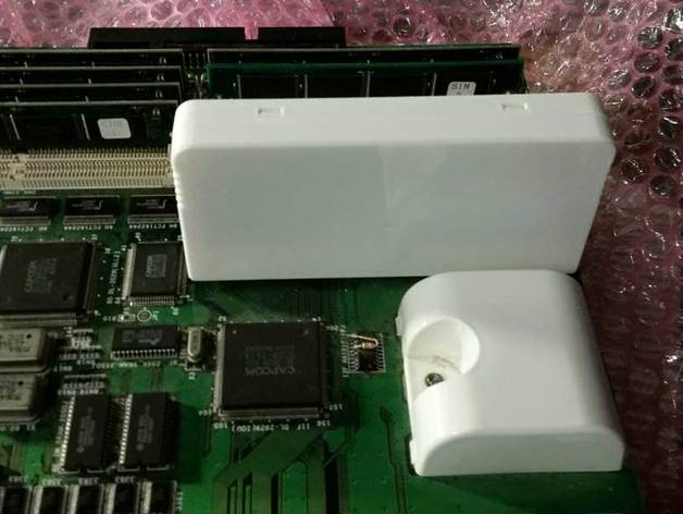
The “battery replacement jig” variants of these parts are to help facilitate a live (powered) battery swap, by providing stabilization to the cartridge PCB and reduce the risk of power loss during a battery replacement which could kill the cartridge.*
*NOTE: please test the stability your printed jig provides before attempting a battery swap, not all 3D printers will provide results consistent with my own. As such I assume no responsibility if a jig printed using these files does not hold the cartridge tight enough to prevent power loss during battery replacement. Use this at your own discretion.
As always these designs are provided free of charge.
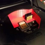
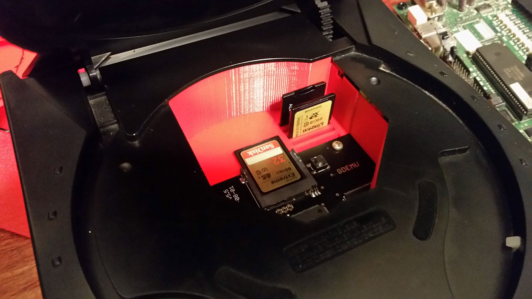
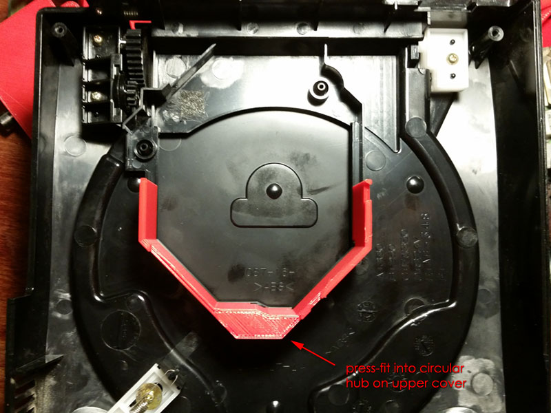
The GD-EMU is an SD card adapter that replace the ever failing GD-ROM drives in Sega Dreamcast consoles. These are great devices but they leave a very large space open inside the console meaning you can easily, accidentally drop your SD card inside the console and be forced to disassemble it to get the card back. These files are to print a tray or finisher pieces that wall off the insides of the console making it not just more professional looking and visually pleasing but also making it impossible to lose a card inside the console. This also makes it easier to insert and remove cards and there are optional spaces provided for additional card storage; making it more versatile as well.
This SD card Tray comes in two pieces. The base bolts to the console in place of the GD-ROM drive and supports the GD-EMU. The shield is press-fit into the lid to finish enclosing off the area making it impossible to drop your SD card inside through an open lid.
There are three different STL files for the base, one includes a set of 4 slots on the left to allow you to store additional SD cards (the slots are staggered to allow easier gripping), another with 5 SD card slots on the right (these are not staggered).. and the third file with no card slots is simply for people who are not interested in this feature.
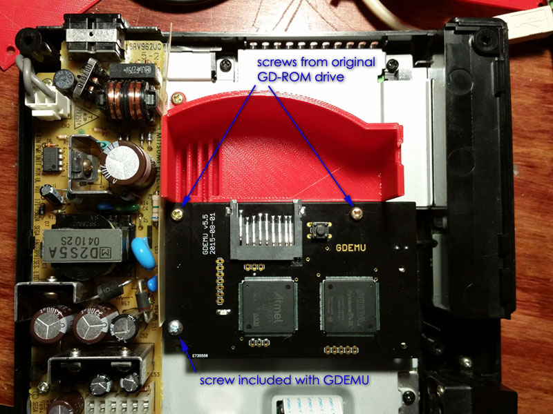
Fitment has been tested on GDEMU Version 5.5. It should work on GD-EMUs version 5.x but will not fit on Version 4.x or older GDEMUs.UPDATE: Files have been added that support version 5.0 GDEMUs (without any screw holes). The originally posted files should work with version 5.1 and newer GDEMUs. It installs using the original hardware that held the GD-ROM drive into the Dreamcast as well as the screw that is included with the GD-EMU So once you print it you should have all the parts you need to install. The only tool you’ll need is a screw driver.
This a synopsis of this project from concept to prototype, I’d like to take it further but I’ve done all I can do given what I know. Hopefully I’ll gain more knowledge and be able to bring this project to completion sometime in the future.
If you don’t know what a Sega Versus City or a Vs Billboard is, here is a brief history lesson:
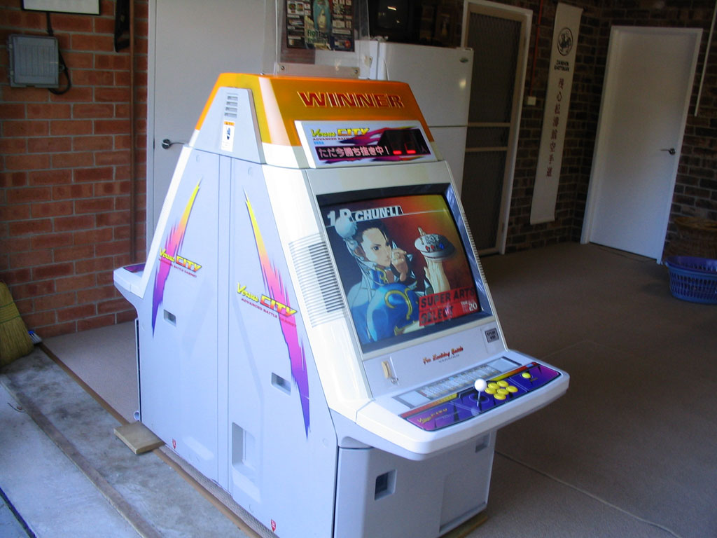
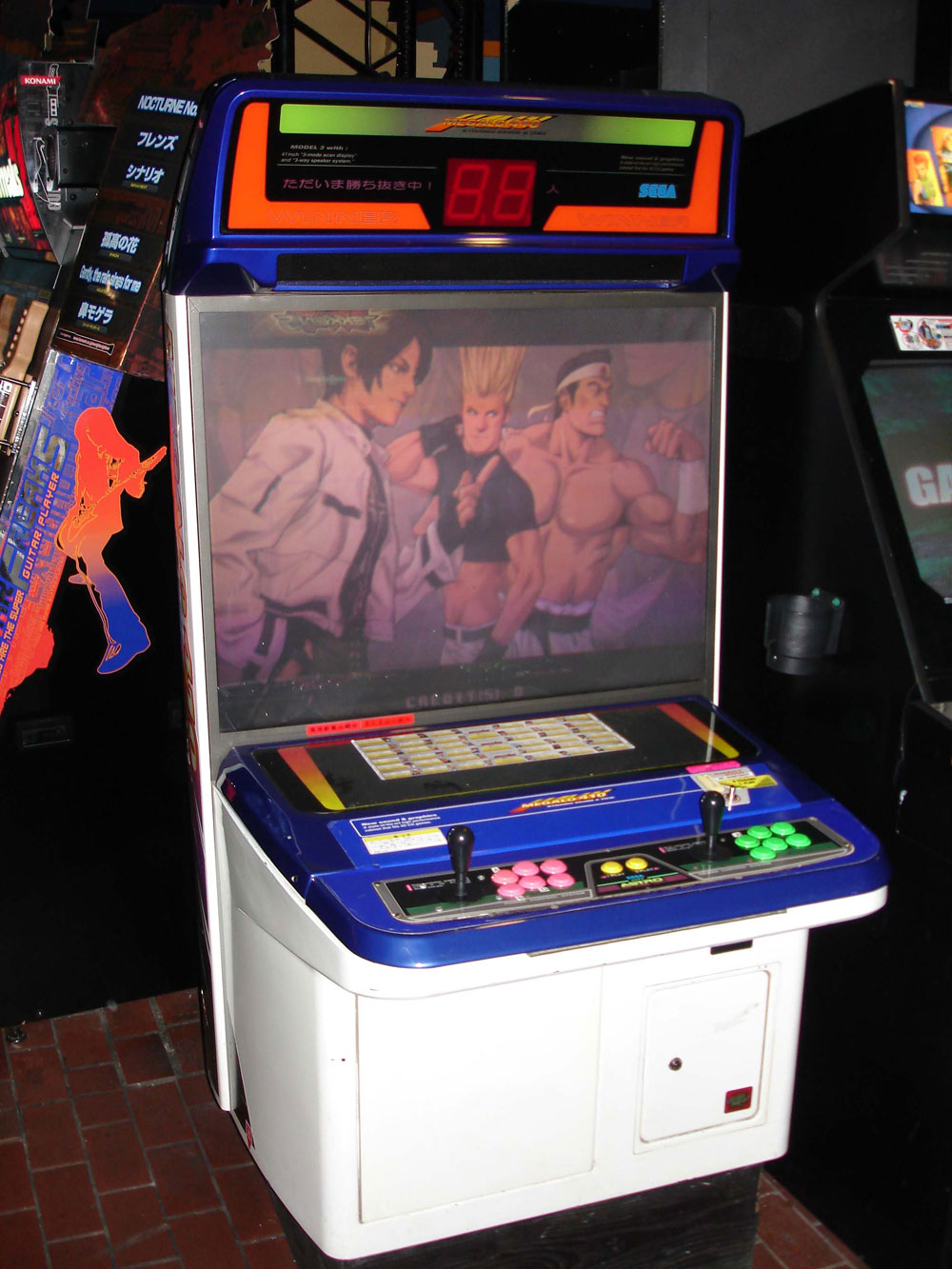
Sometime around 1996 Sega made a “Versus City” arcade cabinet. This was essentially a Siamese-Candy Cabinet; two cabinets back to back merged into one. The idea was for this to be used with games that supported 2 players pitted against each other. In most cases one game PCB could be loaded into the cabinet the video and audio signals split and fed to each side, with each player getting their own dedicated control panel and screen to enjoy the game. Some games that shipped in this cabinet (such as Virtual On) used a separate PCB for each player, but the concept remained the same.
One interesting feature of this cabinet was the “Vs Billboard System”. This included a large “WINNER” lamp for each player as well as a 2-digit 7-Segment display on each side designed to show that player’s consecutive win count. Sega enabled these displays to do much more however, showing off animations and scrolling text, the way each game supported this is different. For games that didn’t support the billboard the system could be set to display a generic Attract mode loop.
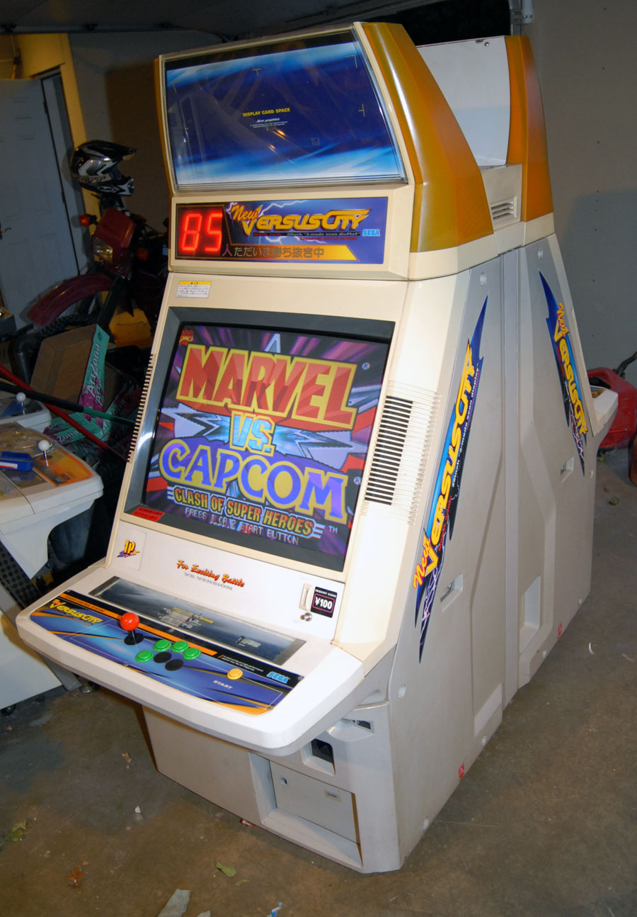
Sega eventually made a follow up cabinet called the “New Versus City” as well as Vs. Billboard upgrades for the Blast City and Megalo 410 cabinets.
What games supported the Vs. Billboard System?:
While the generic “Attract Mode” video above is pretty cool, the billboard system is rather pointless unless it actually functions within the context of a game. Despite seeing many copies of Street Fighter II loaded up in these cabs, that game pre-dates the original Versus City and the Vs. Billboard system by several years and sadly there is no indication I’ve found that ANY Capcom games support it. Looking through the games available on the various Sega hardware platforms starting around 1996 and seeing which games detailed a “Billboard output” option either in the service manual or present in the game test mode. I’ve compiled the following list, though this may not be complete:
Sega ST-V Games:
All Japan Pro Wrestling Featuring Virtua /Zen Nippon Pro-Wrestling
Critter Crusher / Tatakot (maybe? supports 7-seg displays but might not be billboard system)
Hanagumi Taisen Columns : Sakura Wars (needs cabinet type set to vs in game test mode)
Mausuke no Ojama the World / Kiss Off (winner lamp only, I think)
CyberTroopers Virtual-On Oratorio Tangram MSBS 5.66 (needs billboard enabled in game test mode, otherwise it’s winner lamp only)
Virtua Striker 2 Ver.2000
Virtua Tennis
Virtua Tennis 2
Sega NAOMI 2 Games:
Virtua Striker 3
Sega Tri-Force Games:
Virtua Striker 2002
If you know of any other games or other hardware that supports the Vs. Billboard please let me know.
How does the Vs Billboard hook up to these games?
The Vs. Billboard has a control PCB that can run both sides in Versus City cab at the same time. This PCB has 8 digital input pins that can receive commands from the game PCB and properly interpret them into displaying text or animations on the 7-segment displays or flashing the WINNER lamps.
On newer JVS game boards such as the NAOMI and Tri-Force, any JVS I/O board with at least 8-output pins will use those first 8 pins for the Vs. Billboard output. Some games (such as Virtual-On OT 5.66) will need the billboard output enabled before it will start sending data, other games (such as Virtua Tennis) will have billboard output enabled by default. It was originally thought that JVS games required the use of the Sega JVS to JAMMA Rev A I/O board for billboard support, since that was the only board mentioned in the official Sega documentation, but that is likely because all of the billboard enabled cabs were wired for JAMMA and that was the only official Sega JAMMA compatible JVS I/O at the time. (though I should note that particular board does need the jumper JP1 set to position “B” to set the extra pins to output mode instead of input mode).
On the Sega ST-V, connector CN32 is used for billboard output according to official Sega documentation. Though it’s not clear if additional jumpers need to be set to use this as an output port since this connector is often used for player 3 input.
On the Sega Model 2 and Model 3 boards the typical output connector is NOT used for the billboard, instead the billboard output pins are split across 2 connectors using the “4-Bit I/O” pins available on each of the larger Analog input connectors. See my Model 2 and 3 filter-board pinout guide. Model 2 and 3 boards seem to be the only ones that are capable of supporting the billboard in addition to other lights and outputs since the normal 6 pin output connector isn’t used.
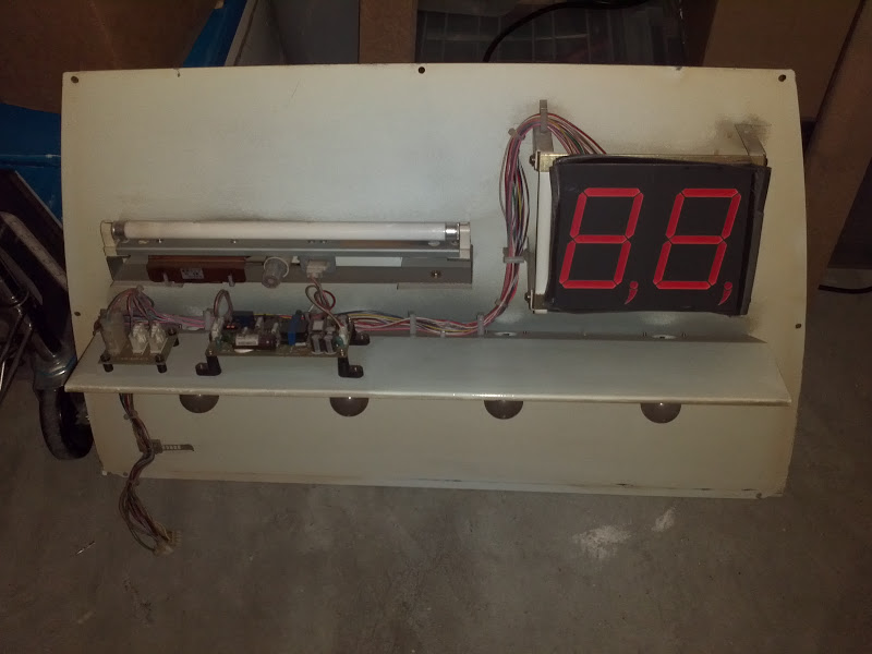
The PCB that controls these look like this:
This is a part number 837-11854 from a Versus City cabinet. The Blast City kit used part number 837-12792-02 which I’ve been unable to find a picture of. I don’t even know the part numbers for the New Versus City or the Megalo 410 kits. The connector on the left is power input. The small black connector is for data input, the large black connector is for output to all the lamps. It’s unclear the function of the dip-switches though I believe they can be used to turn on and off attract mode or (presumably) to configure which side is which player or which side is connected to the control pcb.
What I set out to do: Now that you know what the Vs Billboard system is, what games support it and how it works My goal is simple: Reverse Engineer the billboard control PCB, learn how to interpret the data coming out over those 8-wires and emulate that on an Arduino with some off-the shelf 7-Segment displays and LEDs so that I can build my own Vs. Billboard from scratch and hook up to my (Model 3) Virtual-On OT Twin unit.
The first step was to gather as much information about this as possible. Most of what I learned is outlined above. Then I made some guesses and speculation as to how the data protocol might work given the year in which the first cabs were made, the kind of chips I can see on the PCB pictures as well as the fact that these output ports are typically used for simple light blinking, not data. Some of my guesses turned out to be spot on, others completely wrong. I posted all of my thoughts and discoveries during this process over on Arcade-Projects if you’re interested in the nitty-gritty details.
Correlating the Billboard displays to the data going in: Finding information on this system was fairly difficult, more-so every video I’d ever seen only showed the attract mode of the billboard, never any gameplay output. Speculating as to how things work is one thing but it’s impossible to reverse engineer something without actually knowing what it does; like trying to translate a new language without any context.
The first big break came from someone named majors over on ArcadeOtaku who owns one of these cabs and was kind enough to film Virtua Tennis 2 output to the billboard from test-mode. Now I had something I could actually work with. While I was working on a method of capturing the output data from the game board MetalliC on Arcade-Projects gave me a head start by giving me the raw output hex data from the Demul emulator running the NAOMI version of Virtua Tennis 2 in the same test mode. This was extremely helpful but without knowing how that output data was timed made it difficult to determine which bits of data applied to which change on the screen.
My first test setup was simply attaching each output from the NAOMI to an LED so I could watch the data in binary in real time. I recorded a video of this in slow motion.
You can see in the videos there are some flashes then a pause then some flashes then a pause. This was obviously correlated to each time the numbers changed on the billboard about 1 second apart. I was then able to convert the binary pattern in the LEDs to hex and look for a corresponding hex value in the output data that MetalliC provided. I was able to step frame by frame in the video I shot of the binary output, and then confirm that with the data MetalliC provided. I now also had timing to the data output and was able to piece together a basic code. Further, I ran the test for the player 2 side and even without a video, simply assuming it was the same test pattern on that side I could see the difference in the commands between the player 1 side and the player 2 side.
I from this I figured out that the last 3 bits determine which of the 4 7-segment displays are being updated. and the first 5 bits represent the number being displayed. I also discovered that if you were to invert and reverse the first 5 bits the number simply counted in binary 0000 for “0”, 00001 for “1”, 00010 for “2”, up through 01010 for “A”. I would later discover that this continued through most of the alphabet, albeit with several letters removed such as O, since it looks the same as 0 and there aren’t enough bits to go around for the full alphabet. I’ve been able to extrapolate up through the letter P but after that I’m unsure. since there needs to be at least 4 letters removed after that. Assuming S and Z are two of them since they have the same pattern on a 7-segment display as 5 and 2 but I know it’s not r,T,U,v, or y since those letters are used in the attract mode pattern. That means out of Q, W and X, at least two of those letter’s probably aren’t available.
For the Winner Lamps if the last 4 bits were 0110 then then the first 4 bits were used to control the winner lamps with the 4th bit selecting which side. Interestingly they didn’t send an on, off, on, off, on command to make the lamps blink. Rather they simply send a command to start blinking, and then another command later to stop blinking. My guess is that they wanted to blink the lamps at a rate that was faster then they were able to send data so this was more efficient.
Unlike the letters with only 2 winner lamp commands to go by (“start blinking” and “off”) it’s nearly impossible to extrapolate a pattern for the other winner lamp commands. I’ve observed several different commands come through that I believe are for the winner lamps, one of them I can make an educated guess is simply for “on” but there are at least at least 7 total unique commands per side. These could represent different blink rates, or maybe blink patterns with different on and off timing, or maybe something else altogether. it’s impossible to determine without seeing a video of how the billboard is supposed to react to these commands.
There are several other commands I’ve observed that don’t fit the pattern for the winner lamps or a character output. so I’m at a complete loss for what these do and I’d suspect I wont get much further in this project until I get more video footage of some of these unknown commands, or I manage to get my hands on an actual PCB so I can send it these commands and see what it does (Which would also be nice to confirm some of my educated guesses).
Building the Prototype:
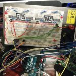
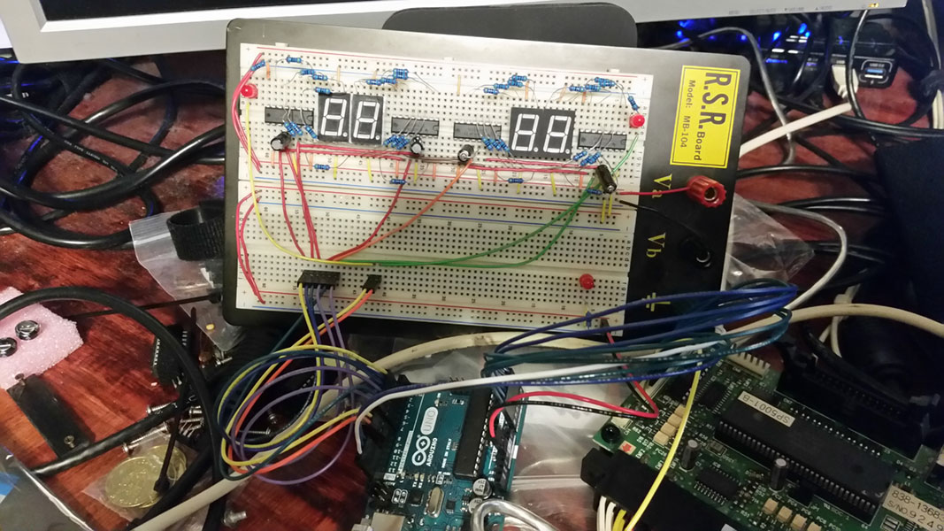
Once I got the Arduino and other parts in I started by programming the Arduino to output to a 7-segment display. I used some shift-registers as described in the ShiftOut example program. this allowed me 32 outputs for the 7-segment displays using only 6 output pins. This could have been reduced to just 3 pins if I chained them all together, but since the commands only specify one character at a time I figured it was much cleaner to make each shift-register/7-segment combo uniquely addressable. Each winner lamp gets it’s own output pin just for simplicity. Here’s what my prototype Vs billboard looks like:
The first program just simulated a few of the attract mode patterns I’d seen in various videos (like the one near the very top of this post). The timing, I’m sure, is way off since I just eye-balled it, but i got to better understand how to output to 7-segment displays through the shift-registers. here’s a brief video of one of the attract mode patterns that I posted to Instagram:
Once I had that down I got set on reading in the actual command data. I quickly discovered that the Arduino was able to read in the data so quickly that I would often read incorrect commands as the data pins were transitioning from one command to the next. I added some code to not act until it read the same command twice in a row there by verifying that it was a legit command. I even setup serial output to display the commands to the serial monitor on my PC with a text description of the command if I knew it, or an “UNKNOWN” text if I did not. When testing this out with various games this let me quickly and easily identify any new and never before seen commands that came through.
To manage the blinking WINNER lamp outputs and allow for blinking at different rates while still checking for new commands constantly I used the millis() counter function to keep track of how long each lamp has been on or off for and check after every loop if it’s time for one or the other to change states.
In any case what I’ve built so far can perfectly replicate the test mode from Virtua Tennis just like the original video I received. Here’s a demo of my Arduino Vs. Billboard running the Virtua Tennis Test mode. You can also see the serial output to my PC. Take note that it can start and stop both sides independently and even blink the WINNER lamps at different timing.
I ignore codes that it doesn’t understand, or in the case of the WINNER lamp commands I simplifying them by programing it to just turn on for anything but the clear command or the one known blink command. Even with only about half of the potential commands known it’s mostly usable. Here’s a demo of it being used in Virtua Striker 3:
If you’re reading this and you know someone who has an original billboard setup that they’d be willing to sell me the control PCB, or even let me borrow it for a few days please let me know. I’d be very interested in getting access to one of these boards to determine the remaining commands and make a 100% compatible Arduino clone.
I don’t want to release my Arduino code publicly until it’s in a more complete form, but if you are so inclined to build your own 7-segment/shift register circuit and would like to play around with it, let me know and I’ll gladly send you what I’ve developed so far.
Expect a follow up post once I have more to share on this project.
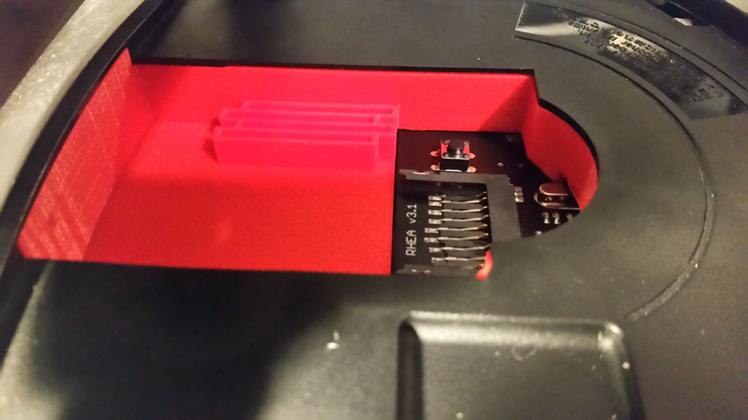
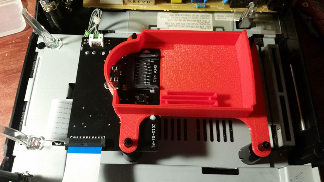
The Rhea and Phoebe devices are SD card adapters that replace the ever failing disc drives in Sega Saturn consoles. These are great devices but they leave a very large space open inside the console meaning you can easily accidentally drop your SD card inside the console and be forced to disassemble it to get the card back. This SD card Tray is designed to fit on top of the Rhea or Phoebe device and seal off the inside of the console making it impossible to drop your SD card inside through an open lid.
I also included a set of 4 slots to allow you to store additional SD cards in the space available, the slots are staggered to allow easier gripping and they’re placed such that when the lid is closed it will keep them from falling out even if the console is turned upside down. There is a second file available without these slots for people who are not interested in this feature.
Fitment has been tested and confirmed on VA0 and VA1 console revisions with a Rhea version 3.1. the VA2-VA5 console version that require Phoebe haven’t been tested yet but they should fit as dimensionally they should be the same.
UPDATE: I’ve made a version 2 of this that holds the Rhea/Phoebe unit more firmly in place, offers superior fitment, and better looking SD card holder slots.
I recently needed to convert a Sega twin unit arcade machine that had model 2 boards to one that used model 3 boards. I found it really difficult to find information on which pins do what on the filter boards so to get my head around how to change the wiring I made my own diagrams since none seemed to exist.
Model 2A, Model 2B/2C and Model 3 all use the same connectors for everything except for power. the only difference is the connector locations. The power connectors that have a line through them are for output; typically used to power another board somewhere.
If you find any errors in these please let me know.
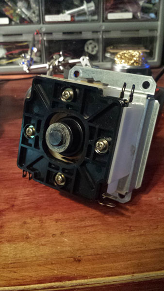
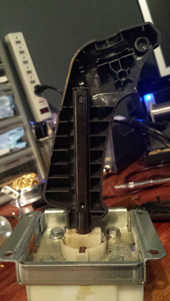
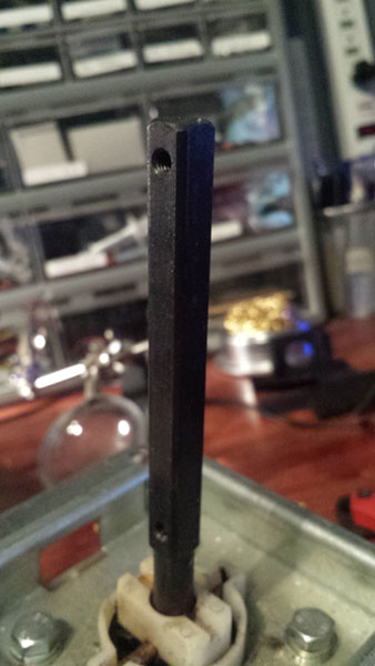
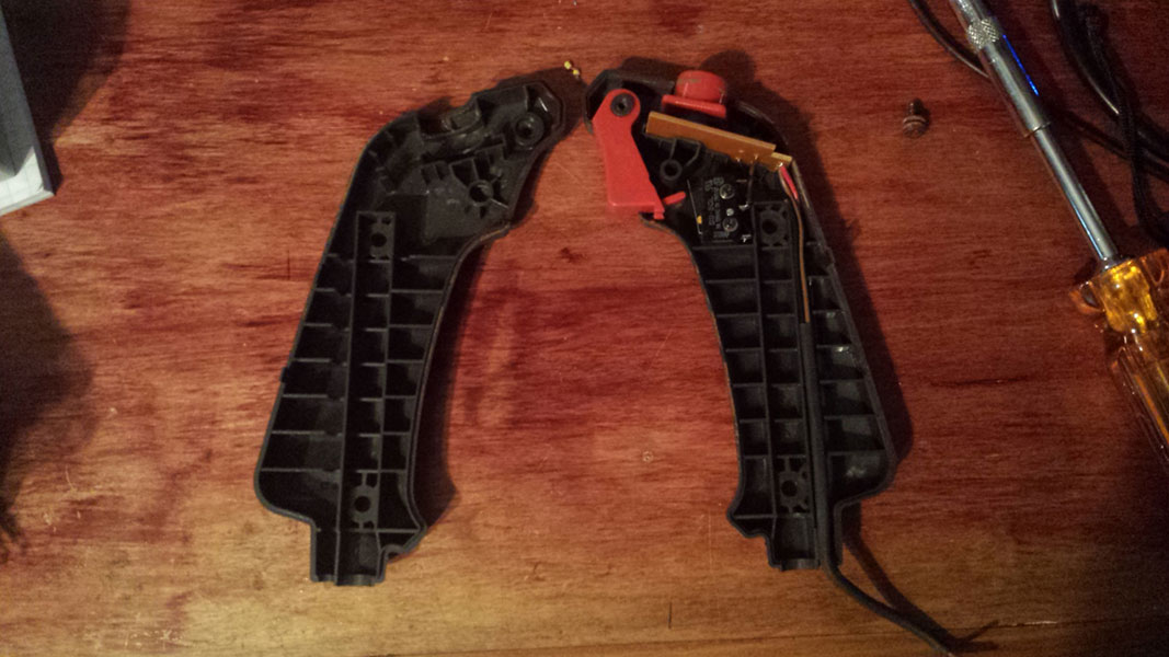
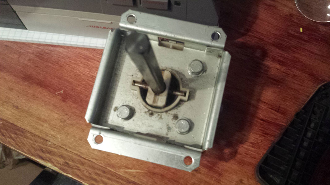
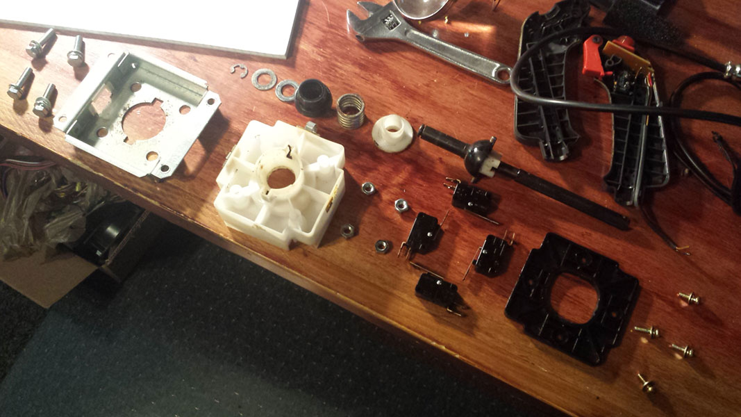
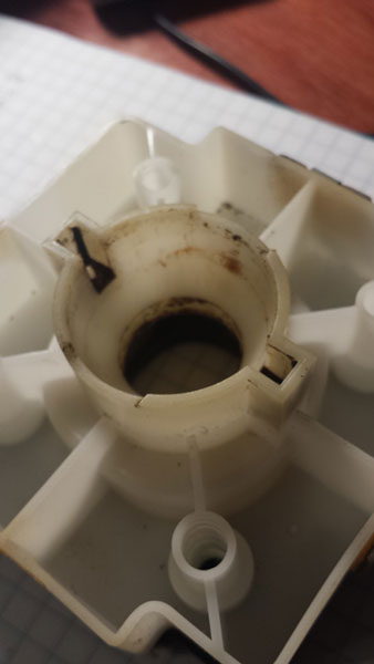
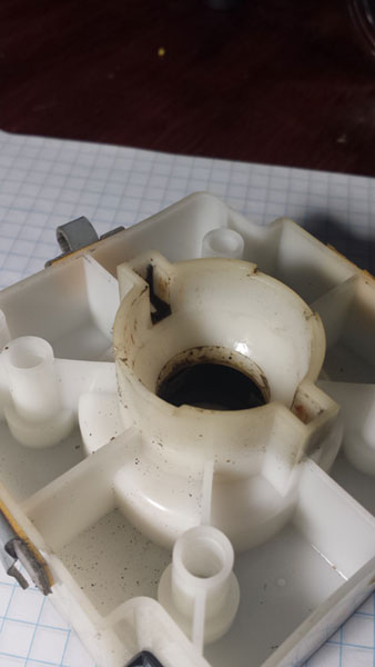
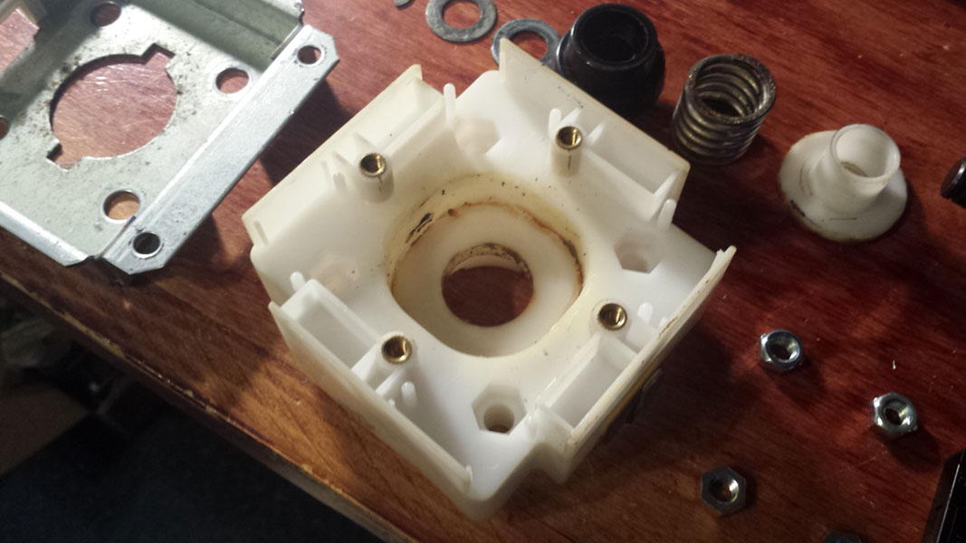
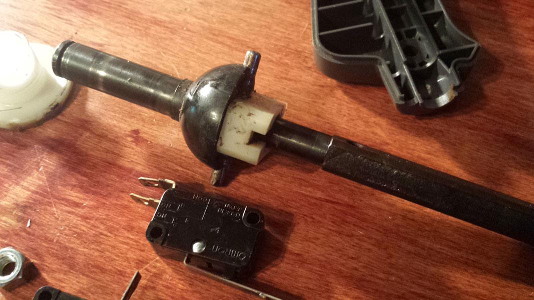
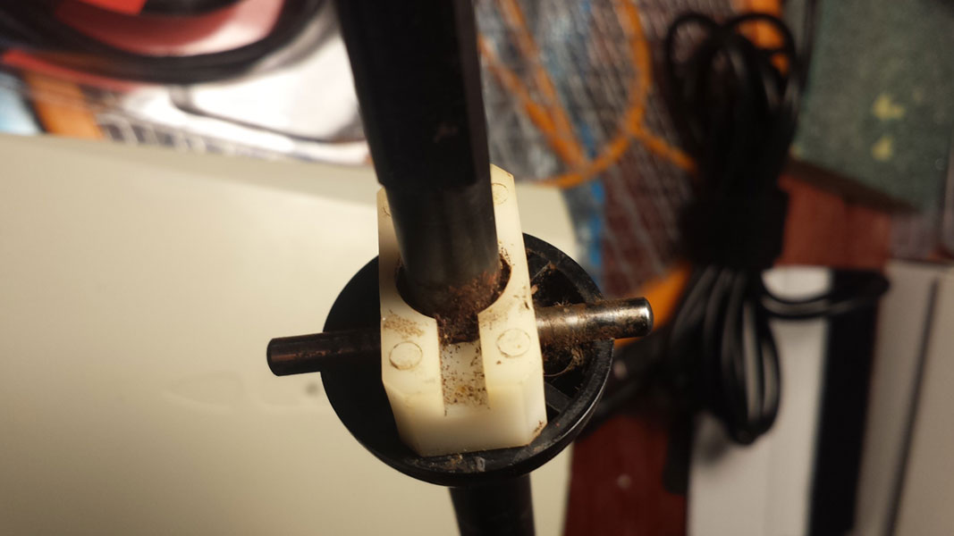
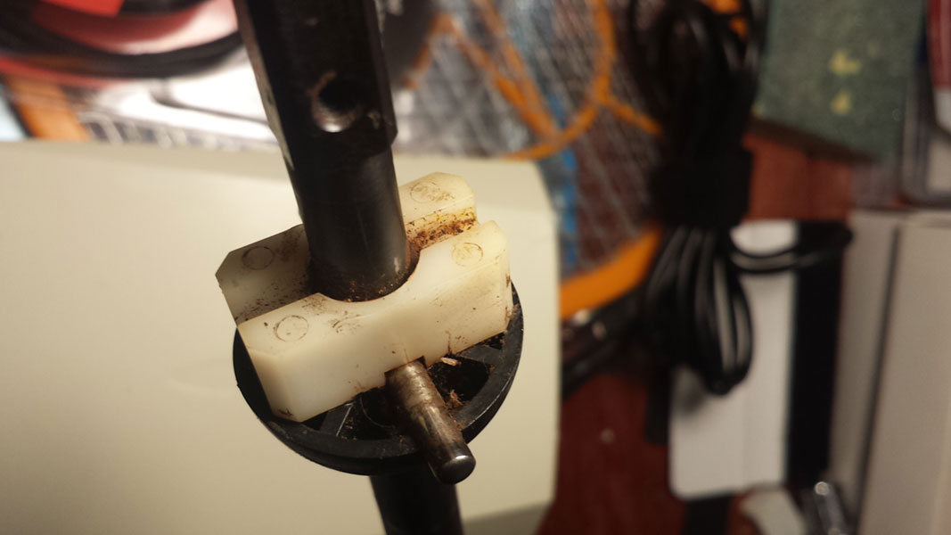
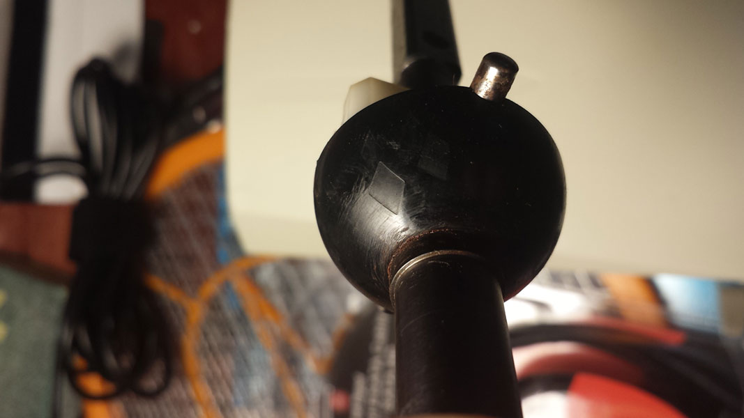
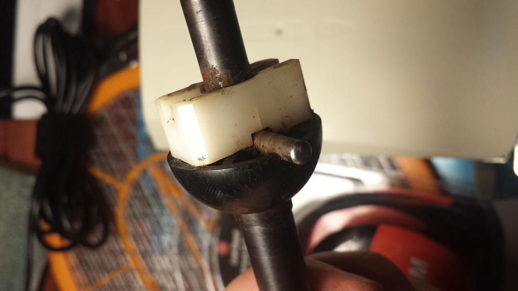
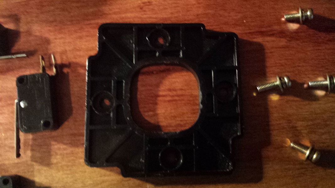
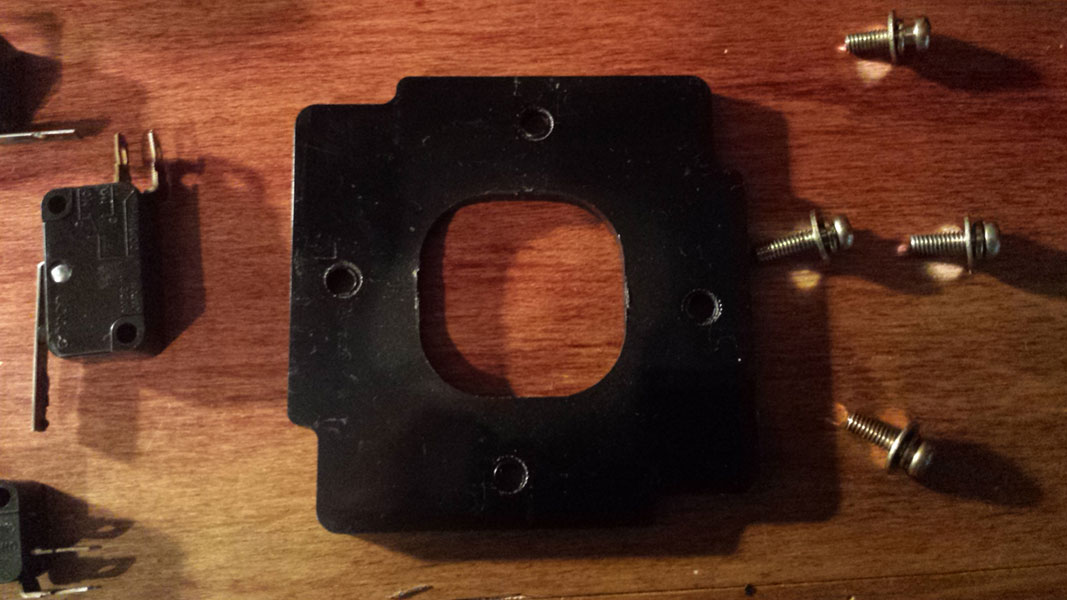
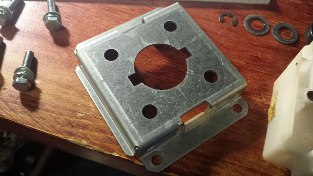
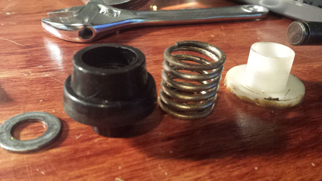
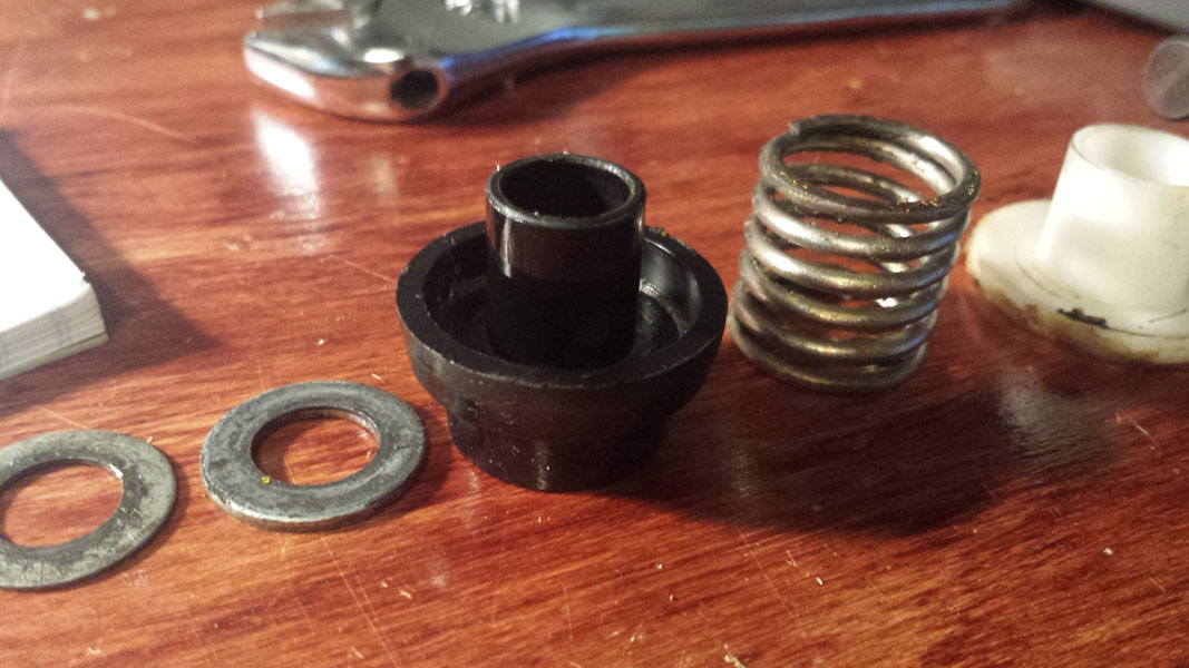
This is an actual arcade stick from a Japanese Virtual On Oratorio Tangram (VOOT) arcade machine. I believe these are also used on Outrigger arcade machines and the sticks used on Virtual On Force are very similar, only differing in color and the style of the thumb button. These are completely different than the home-use sticks for Saturn, Dreamcast, PC and even the newer Hori twins-sticks which use Sanwa Parts.
If you or anyone you know owns one or more of these sticks, or even just parts and are willing to sell please get in contact with me.
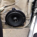
I have a 2nd Gen (1995-1999 BD/BG) Subaru Legacy Wagon and I wanted to installed some 6.5″ Alpine (SPS-610) speakers in all of the doors. It seems although there are many places that sell speaker spacers/adapters for Subarus, no one makes adapters for the rear doors on this generation of Legacy. Apparently most Subarus share identical speaker mounting except for the rear Legacy speakers, they’re a different shape and no one has bothered to make adapters specific for this car.
I recently bought a 3D printer so I decided to make some.
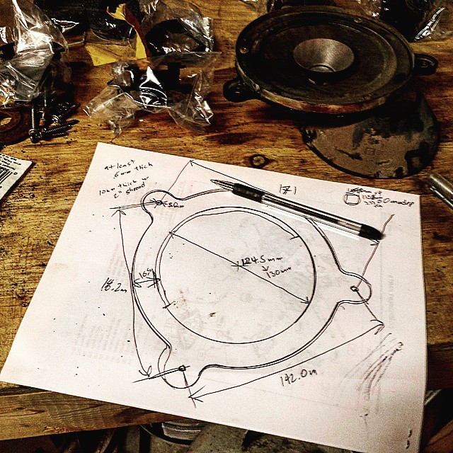
First I took some measurements of the opening in the door, and the spacing between the factory speaker screw mounts. I also measured the depth and basket diameter of my speaker and estimated the depth available in the door with the window down. Finally I estimated the space available between the factory speaker grill and the door itself to make sure I’d have enough room. and I drew up a sketch with some notes.
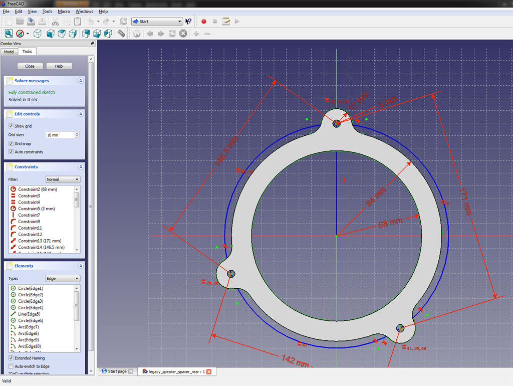
Next I used FreeCAD to convert my sketch into a digital sketch. I had never used FreeCAD before but I had heard it was similar to SolidWorks (which I am familiar with) so I decided to try it. It’s not nearly as good as SolidWorks but it worked well enough to do what I needed to do.
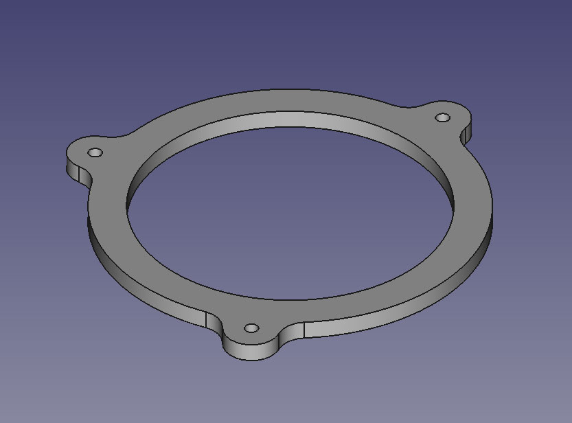
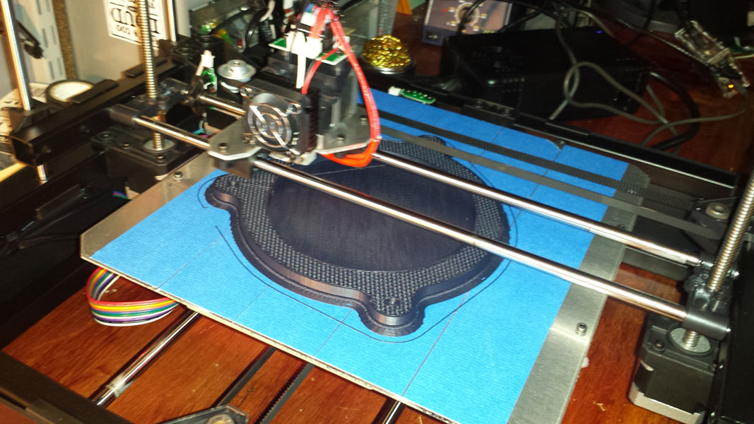
Once the sketch was complete I converted to 3D geometry and exported as an STL file for the 3D print.
The STL file is then converted to G-Code instructions that the printer can read to create the object.
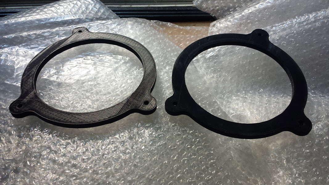
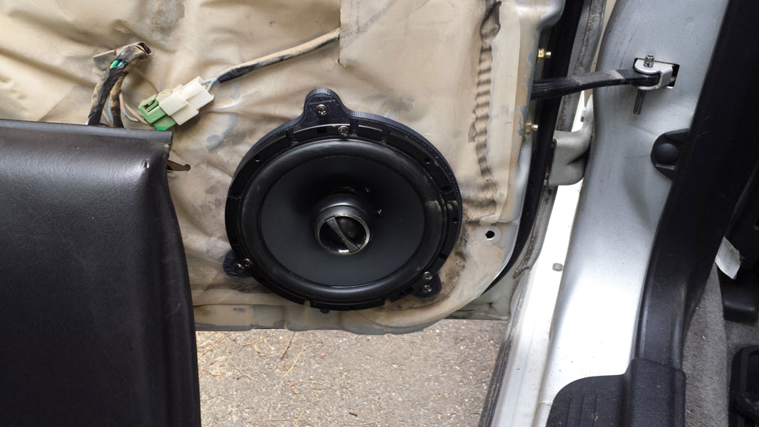
My first version was actually a little too thick, it rubbed up against the back of the speaker grill, So I remeasured, adjusted the 3D model and re-printed… the final result fits flawlessly and mounts up just like the OEM speakers.
I used some Metra wire adapters to make the whole thing plug-n-play.
If you’re interested in printing your own you can get the files on Thingiverse. I do have some of these pre-printed if you want a pair I will ship them anywhere in the USA for $15.
For a while now I’ve needed to map out the dimensions of my Killer Instinct 2 arcade machine so that I can print out new artwork and ensure that the button and joystick holes all line up. To do this I created a pair of bulls-eye hole center finders. I got the idea from Pocket83 on Youtube here:
For My hole centers I used clear “Binding Covers” that I bought at Staples, these are essentially thicker versions of transparency paper. Using this material instead meant that I could have some overlap between the bulls-eyes without much trouble. I also marked circles at 24mm 30mm and 57mm as these are either exactly or very close to the most common hole sizes you’ll find in a control panel. I found the center hole finders are actually extremely accurate and I used a level to ensure that both the machine and the center lines were horizontal for accurate off-set measuring.
Here are the dimensions and button positions of the KI2 control panel (should be the same for KI2) Units are in inches, and everything is to the nearest 1/16th.
I also have a Mortal Kombat 3 machine at my disposal so I took the liberty of mapping out the dimensions of that as well:
This should be similar for other Midway games from that era. MK4 should be identical except for the placement of the start buttons. War God should be the same. And MK1 MK2 and Wrestlemania should be the same except without the run button.
Hopefully others will find this information useful, I know I looked everywhere for dimensions on these control panels to no avail before taking the time to measure them myself.
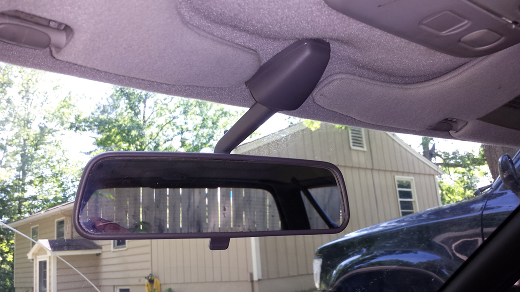
I have a 99 Subaru Legacy wagon with a pretty common problem. The rear-view mirror in these cars likes to droop, it adjusts itself downward whenever you go over bumps. It’s a problem that seems to effect all of 2nd generation legacys (1995-1999 aka the BD or BG chassis). It’s mostly due to the design of the mirror, the ball joint is on the back of the mirror rather than the top, which means in order for it to hold it’s position there needs to be a lot of tension in the joint in order to resist the force generated by the weight of the mirror whenever the car hits a bump.
Having owned several 240SXs I noticed that the S14 chassis (1995-1998) uses a very similar size and shape mirror as the 2nd gen Legacy:
As you can see they both use a similar length arm with a similar shaped mirror and a similar 3-bolt mounting flange. The Legacy mirror is black but the gray color of the 240SX mirror doesn’t matter because it actually matches the gray headliner in the legacy.
What’s not the same about the mirrors the adjustment join:
As you can see the 240SX mirror has the adjustment joint on the top of the mirror which means that any bumps or vibrations will have little effect on the adjustment. Having owned 3 separate S14s I never had any problems with the mirror falling out of adjustment, nor have I ever heard of it being a problem with other owners.
AMAZINGLY the bolt holes on the mounting flange line up perfectly in the Subaru for a 100% bolt on replacement. I used the plastic cover from the S14 mirror since the mounting flanges are shaped slightly different but it looks right at home in the Subaru, and no more droopy mirror.
I have a Dance Dance Revolution machine that I installed a PC in to play StepMaia instead. I wanted to get full light output working on StepMania only to discover that because of the way it was programmed the port addresses are hard-coded and because my StepMania PC uses a PCI based parallel port card I would have to modify the source and recompile…
I thought this was a exceedingly DUMB design so I did something about it.
I have some programming abilities (albeit not with C++) so rather than modify the source I decided to write a new parallel_lights_io.dll that works the way SM should have worked from the start. That way anyone who wants to add light output to SM can do so by simply adding these files to to their installation directory. Basically all this does is provide you with a .ini file that you can modify with your port addresses instead of having to do it in your source code. (also it uses the freely available and better inpout32.dll instead of the licensed and buggy io.dll that SM was built to use)
If anyone is interested in the source code let me know.
Supported Versions:
This is tested and working on SM 3.9 Plus Redux and OpenITG Beta 2 in Windows XP… I wont work on any version that has light output intentionally disabled in source (which means vanilla SM 3.9 and 4.0 will not work) I haven’t tested it on any other releases or OSs…
If you’re using a Linux build then you don’t need this… this is only for Windows.
If you’re at all interested in getting light output working please feel free to download and try this out… I’m interested to see how it works for other people. You’ll obviously need some hardware output on your parallel ports to see it working.
Hardware:
I’m using a Rosewill RC-304 dual parallel port PCI card (it’s also low-profile if you’re using a half-height PC case) though any properly installed parallel ports should work
If your intention is to hook this up to a real DDR Arcade machine. DDR has a light driver board already installed, you simply need to invert the parallel port outputs by using an opto-isolator OR a few 74 series inverter chips…. OR utilize the transistor/diode/resistor circuit for relay output described in the link above. The circuit requires a lot more soldering but I’m using that because it’s self-powered from the parallel port which makes for a cleaner install (opt-isolators or inverter chips would require an outside power source)… the DDR driver boards don’t draw much current, they’re just checking for an on/off value on the pin…. If you try to power a lamp any larger than an LED then you’ll likely blow out your parallel port which would be bad.
Here are the pinouts for the DDR light connectors as well as the parallel port pins used by StepMania: Player 1 Platform Lights (10-pin White Connector)
1 black logical ground
2 green-red player 1 up arrow lights
3 blue-red player 1 down arrow lights
4 purple-red player 1 left arrow lights
5 gray-red player 1 right arrow lights
6 white enable pad (tie to logical ground)
7 brown (unknown)
8 N/C
9 N/C
10 N/C
Player 2 Platform Lights (10-pin Orange Connector)
1 black logical ground
2 green-red player 2 up arrow lights
3 blue-red player 2 down arrow lights
4 purple-red player 2 left arrow lights
5 gray-red player 2 right arrow lights
6 white enable pad (tie to logical ground)
7 brown (unknown)
8 N/C
9 N/C
10 N/C
Cabinet Lights (10-pin Red Connector)
1 black logical ground
2 N/C
3 N/C
4 purple-brown player 1 button lights
5 gray-brown player 2 button lights
6 green marquee lower right floodlight
7 blue marquee upper right floodlight
8 purple-red marque lower left floodlight
9 gray-red marquee upper left floodlight
10 green/yellow earth ground
Sub Woofer Lights (6-pin White Connector)
1 black logical ground
2 gray subwoofer lights (both)
3 N/C
4 N/C
5 N/C
6 N/C
For reference here are the parallel port pinouts for stepmania 3.9
SM Parallel Light Output Parallel Port 1 (LPT1):
1 N/C
2 marquee upper left floodlight
3 marquee upper right floodlight
4 marquee lower left floodlight
5 marquee lower right floodlight
6 player 1 button lights
7 player 2 button lights
8 subwoofer light left
9 subwoofer light right
10-17 N/C
18-25 logical ground
Parallel Port 2 (LPT2):
1 N/C
2 player 1 left arrow lights
3 player 1 right arrow lights
4 player 1 up arrow lights
5 player 1 down arrow lights
6 player 2 left arrow lights
7 player 2 right arrow lights
8 player 2 up arrow lights
9 player 2 down arrow lights
10-17 N/C
18-25 logical ground
I’m also opting to go with 36-pin Centronics connectors on my light board so that I can use off-the-shelf printer cables… for reference here is how the DB-25 (parallel port) connector maps to a Centronics-36: http://www.lammertbies.nl/comm/cable/parallel.html
The Centroincs 36-pin connector ends up being mapped out like this:
Output pins (same numbers as DB-25): 2-9
Ground pins: 16-17, 19-30, 33
Pins with No Connection: 1, 10-15, 18, 31-32, 34-36
Parallel Port Hardware Testing:
If you’re having problems and you want to test your hardware with a program other than StepMania then I recommend this app: http://lpt-port-test-utility.software.informer.com/3.0/
I used that myself quite a bit when developing this little dll. you just plug in your port address and you can turn on and off the output pins on the parallel port to test out your hardware without the use of StepMania.
—————
I’m just happy to get this working for myself but if it this helps someone else then that’s even better…
Consider anything I share here free for public use. The only thing I ask is that you link back to the relevant page here, or at very least tell them that "twistedsymphony" created it.
If you find something I've done here useful and would like to buy me some caffeine/more hardware/new tools/or just help pay the server bill, you can paypal.me.
thanks.