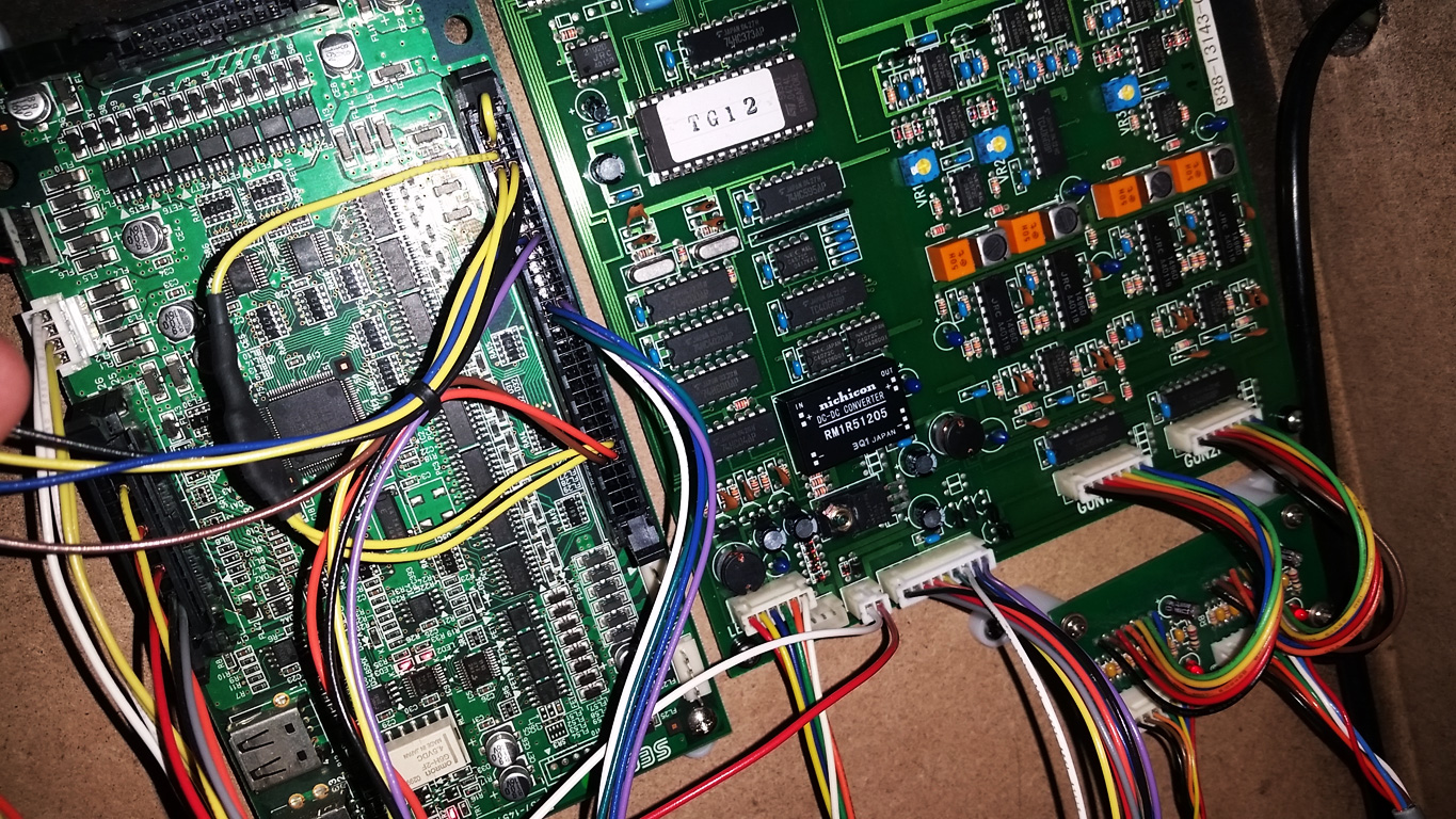
In Part 2 I broke down the details of the LED board, in Part 3 I broke down the details of the Sega/IR Sensor Board. Here in Part 4 I’m going to cover the Gun Sense Board and Protection Board
As stated in part 1 there are essentially 3 parts to this setup,
1. A chain of 10 or 12 Addressable IR LED boards explicitly positioned around the parameter of the display
2. IR motion sensors in the gun housings.
3. the “Gun Sense” board (essentially the Gun IO).
In this Part I’m going to discuss the Gun Sense Board; often referred to as the “Gun IO”.
Analog Communication vs Serial Communication
There are many variations of these PCBs and just like the LED boards an IR Sensor Board the Gun Sense Boards are largely interchangeable and cross-compatible. However, While most Sega Gun Sense Boards from Model 3 up through the Lindbergh operate by providing it’s gun position data with an analog signal, some other versions do not produce an analog output but instead transmit their positional information via a RS-232 Serial Connection.
It’s unclear if all serial type boards output data the same way. Some time in the future, I might tackle that subject, but for the sake of this write up we will only be covering the “analog output” systems. Though in the “board variations” section at the end I will show both types so that you can easily tell them apart.
LEDs and Sensors from a “serial output” system should still be compatible with an “analog output” gun sense board, it’s just that the gun sense board needs to be matched to the requirements of your game board. Any game that uses analog inputs for it’s gun positioning (whether it originally shipped with a Sega/OHMIC setup or not) should be compatible with an “analog output” type gun sense board.
Pinout and Wiring
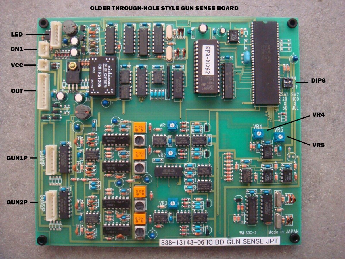
This pinout information is primarily for the older 838-13146 / 838-13143-## PCBs These are easily identified as they use the larger through-hole style components as seen below.
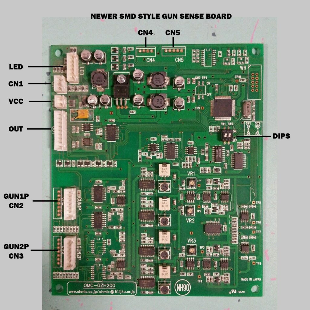
The newer style SMD gun sense board shipped in a number of different configurations. The one below is setup for analog output and was used on Time Crisis 4 as well as Lindbergh and RingWide era Sega releases. However some other titles used this board in a serial configuration with the “OUT” connector not populated and CN4 and CN5 populated instead. The pinout on this does have some minor differences in the gun connector from the older through-hole style PCB above, and those differences are noted in the pinout information below.
LED: 6-Pin JST XH connector.
This is the output connector for the LED board chain. As stated in Part 2, this connector is pinned backward from the LED boards.
- +12V (red)
- +5V (yellow)
- C (blue)
- B (green)
- A (orange)
- GND (white)
CN1: 3-Pin JST XH connector
“Frequency Change” Connector. This connector is meant to be used as a jumper. You’ll find a lot of boards with a loop-back connector jumping pins 1 and 2. Jumping these modifies the LED pattern somehow to mitigate problems with interference should there be two IR Gun cabinets placed side by side. The idea is to alternate cabinets with and without the jumper. For instance on Time Crisis 4, Player 1 does not have the jumper and Player 2 does. Generally one of these pins is tied to +5V and the other is routed to the CPU, which pin is which changes depending on the PCB revision.
- Frequency Loop Back
- Frequency Loop Back
- (N/C)
VCC: 2-Pin JST XH connector
This connector is the power input connector to the Gun Sense Board.
- GND (white)
- +12V (red)
OUT: 9-Pin JST XH connector
This connector is for the output from the Gun sense board, to be routed to the input (or JVS IO) of your game board. These are all output only, so the Gun Sense board doesn’t care if they’re hooked up or not.
- Ground Reference (white/brown)
- Player 1 X Position (gray) [5V analog]
- Player 1 Y Position (gray/red) [5V analog]
- Player 2 X Position (orange) [5V analog]
- Player 2 Y Position (orange/red) [5V analog]
- Player 1 Frame Out (green) [digital]
- Player 2 Frame Out (green/white) [digital]
- Player 1 Trigger (yellow) [digital]
- Player 2 Trigger (yellow/white) [digital]
GUN: 2X 7-Pin JST XH connectors
One connector per gun, this is the input from the IR Sensor module. Both connectors are pinned the same. It’s also important to note that the VCC out pin provide different voltage level depending on the Gun Sense PCB variant. Both will work with the older style Sega Sensors, but newer Sensors designed for 5V should only be used with the newer style (5V) Gun Sense Boards.
- Trigger (black) [optional, does not need to be hooked up to function]
- E (brown) [GND]
- D (orange)
- C (green)
- B (yellow)
- A (blue)
- VCC out (red) [this is +12V on through-hole PCBs, +5V on SMD PCBs]
Settings and Adjustments
There isn’t much configuration on this PCB but here is what’s available.
Dip switch 1:
ON/”29″ = For use in Mirror Cab, this will invert one of the axis
OFF/”50″ = For use with a non-mirror cab, this will track the axis normally
Dip switch 2:
ON/”HOD” = for use with 10 LED module configuration
OFF/”JUL” = for use with 12 LED module configuration
The labels and functions of these switches get their roots in the early days of this board. Jurassic Park The Lost World (shortened to JUL) used 12 LED modules while the next game to use this board: House of the Dead 2 (shortened to HOD) used 10 LED modules. Both of these games were sold in a mirror cab with a “29” in monitor as well as a “50” in rear-projection version, hence the 29/50 dip.
VR4 and VR5
These are only available on the older through-hole variant of the PCB, VR4 adjusts the Y-axis offset for both guns and VR5 adjusts the X-
axis offset for both guns. It’s recommended that you only ever touch these if there is a problem and you should mark their position before moving them
The remaining adjustment pots on these PCBs are undocumented but the conventional wisdom is that they’re set at the factory and shouldn’t ever need to be adjusted.
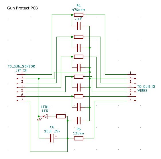
The Protect PCB
With the release of House of the Dead 3 on Chihiro Sega started including a small “Gun Protect” PCB with all of the IR Light Gun games. This PCB was also offered for sale separately for their older IR Light Gun games. The purpose of the PCB is to protect the IR Sensors in the guns from voltage spikes that could kill them.
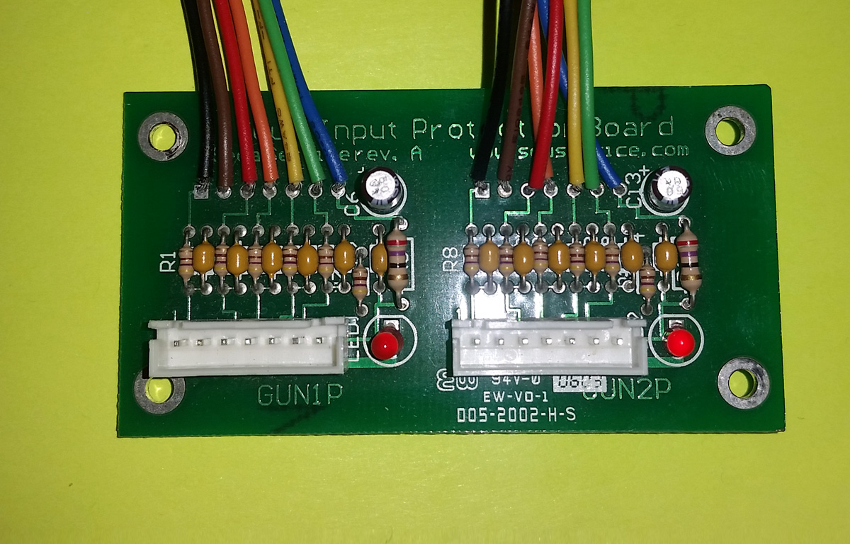
The text obscured by the wires reads:
Gun Input Protection Board
Sega Servicerev. A www.seuservice.com
The Protect Board is a simple filter board that plugs in between the IR Sensors and the Gun Sense PCB. These are highly recommended for anyone running the older style through-hole Gun Sense boards, however Sega no longer used these once they moved to the newer SMD style Gun Sense boards so presumably the issue was fixed on those.
These PCBs can be difficult to find so I mapped out the schematic should anyone want to attempt making their own.
Upgrading
Older Through-hole style Gun Sense PCBs ( 838-13143-## ) mostly only differ by their firmware. Versions -01 through -03 were configured for 12 LED modules only and did not include the option to switch to a 10 LED module configuration. Versions -04 through -11 (which i believe was the last through-hole board revision) differ only in their firmware, and you can upgrade the firmware yourself by simply re-writing the socketed EPROM.
Upgrading to the newer SMD style PCB (like the one shown in the pinout section above) should be a drop-in replacement for the older through-hole style PCBs.
Troubleshooting
If you’re having issues with your Gun setup I recommend first reading the troubleshooting sections for the LED modules and IR Sensor modules. Also verify that the dip switches are set properly on your Gun Sense Board. If you’re having tracking issues you may want to try the LED Frequency Loop Back in both configurations.
If you have a completely dead Gun Sense board I’d recommend checking the 5V regulator. These PCBs accept 12V input power but then generate their own 5V for the components that need it. More than once I found no output on the 5V regulator and was able to revive a dead gun Sense PCB by replacing this component. I don’t have much repair advice beyond that.
Non-Standard Gun Sense Board Variations
Above I’ve covered the versions of this setup you can expect to find on most Sega games, however there are other games that use a variation of this setup.
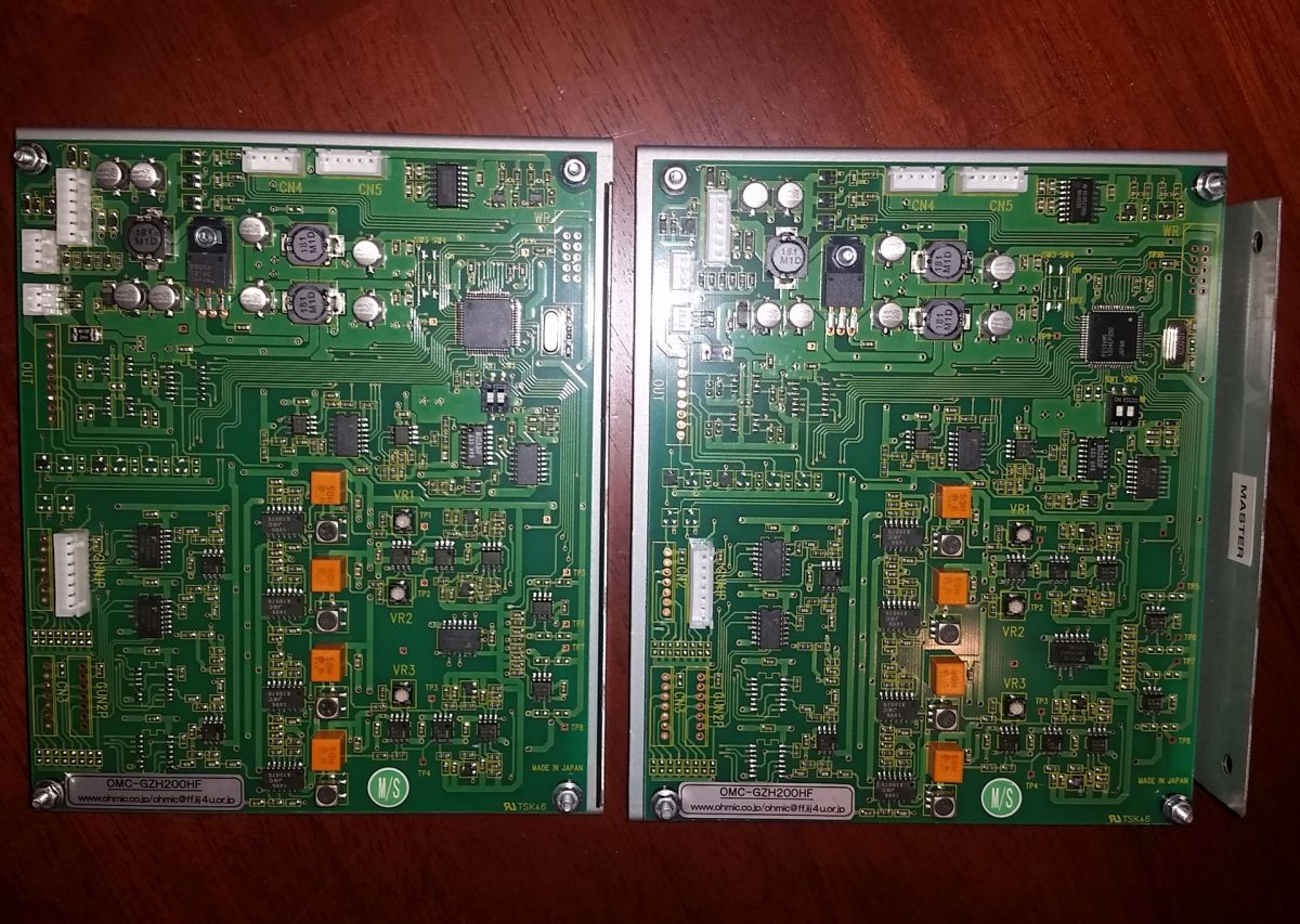
These 2 boards are used by Taito/Square Enix Gun Singer Stratos, Notice that these are similar to the newer SMD style PCB except it’s setup for serial output rather than analog output. This also uses a linked Gun-Sense boar setup with a “Master” board controlling the LEDs and calculating the position of Gun 1 and a “Slave” board calculating the position of Gun 2. Each board has it’s own Serial output.
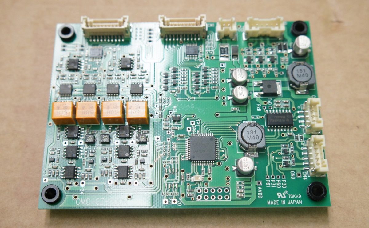
This is the Gun Sense Board used on Time Crisis 5, it’s a much more compact version of the SMD board but it also only offers a serial output connection with no analog output option available.

This is the “Sense Board” used by Sega’s Samba De Amigo. This is a very peculiar setup where the IR sensors were mounted to the left and right sides of the monitor and the maraca controllers had IR LEDs embedded in them. So while based on the same technology as the Gun games, and using the same IR sensor boards, the Sense board is designed to function very different and provide a very different type of output.
Part Number Reference and Final Thoughts
I’ve compiled a spreadsheet of the official part numbers used on every OHMIC based arcade cabinet I know of. If you have additional information or corrections you’d like to contribute to the spread sheet or any part of this guide please let me know. It’s important to me that the information I share is as complete and as accurate as I can make it.
Hopefully if you’re looking to piece together a Sega Type II IR or other OHMIC based Light Gun setup or just interested in how this technology works this guide has provided some helpful information.
Happy Shooting.
0 Responses to “Everything you’d want to know about Sega Type II IR Light Guns. Part 4: The Gun Sense Board”