In Part 2 I started breaking down the technical details with the Sega/OHMIC IR LED boards. Here in Part 3 I’m going to continue breaking down the technical details.
As stated in part 1 there are essentially 3 parts to this setup,
1. A chain of 10 or 12 Addressable IR LED boards explicitly positioned around the parameter of the display
2. IR sensors in the gun housings.
3. the “Gun Sense” board (essentially the Gun IO).
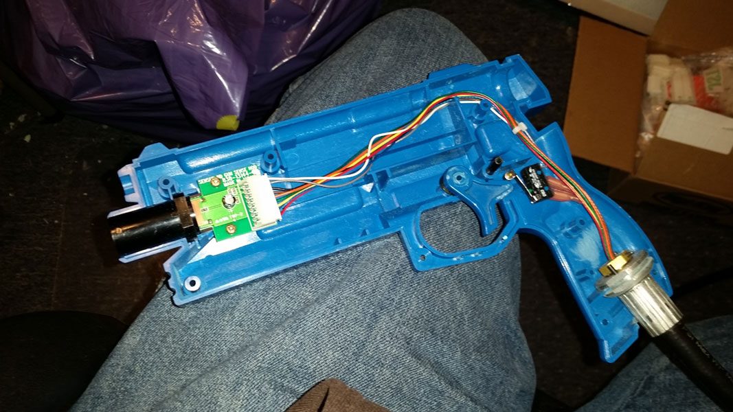
In this Part I’m going to discuss the IR sensors found in the gun housings.
Pinout and Wiring
To My knowledge Sega used essentially the same IR sensor in nearly every one of their IR Light Gun games. Some had different model numbers but the PCB layout, features and shape was always the same.
For the 838-14144 / JPT-2030 / OMJ-GZH200D sensors
These use a 9-Pin JST XH connector and like the LED board the function of the data pins is largely unknown, but the pinout is as follows:
- VCC in (red) [+12V]
- A (blue)
- B (yellow)
- C (green)
- D (orange)
- E (brown) [GND]
- Trigger Output (black)
- Trigger Switch COM (gray)
- Trigger Switch NO (white)
As you can see the trigger switch is designed to pass through this. It’s inconsequential to the function of the sensor though, you can leave pins 7, 8, and 9 disconnected and the sensor will function normally.
The voltage on Pin 1 is also worth noting. older sensors received +12V on this pin and newer gun sense boards started outputting +5V instead (while still using older sensors). Then newer sensors switched to only working with +5V. Safest option is to just run at +5V when possible but if you have an older Gun Sense board, be careful not to send +12V to a newer +5V sensor.
Under the Cover
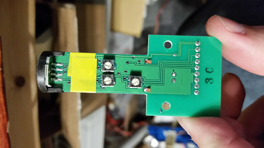
The inner workings of this board are not documented anywhere to my knowledge but I did remove the IR shield (the large seemingly black plastic bit) and the electrical shield (a thin, grounded, copper plate covering some of the sensitive electronics) on one of my sensors to get some photos of the naked PCB.


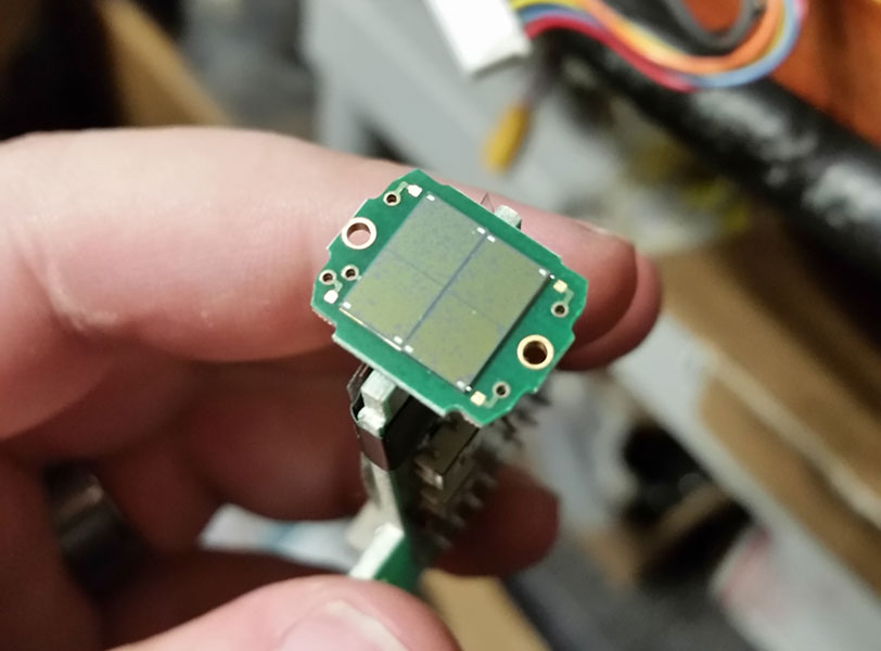
Last year I was shown some photos from a broken sensor out of a Sega Golden Gun machine (below). You can see that aside from the different model connector and the use of SMD components the design is largely unchanged despite the 13 year gap between The Lost World and Golden Gun.
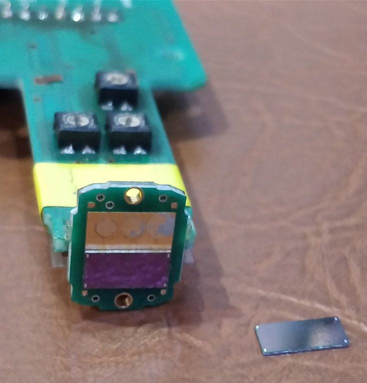
It’s unknown what the function of the 3 adjustment pots are but the conventional wisdom is that they’re set at the factory and should never need to be adjusted.
Troubleshooting
The first thing you should check with the sensors is that the crimps are good on the Sensor connector. The original Sega gun harnesses were prone to have bad crimps from the factory, similarly the “gun hose” is one of the most abused part of a gun cabinet in the arcade, and the constant flexing will cause the wires to fail eventually. So verifying good continuity through all of the wires in the gun harness is a good first step.
Once you’ve verified that the wiring is good the next best step is to clean and polish the black plastic housing on the sensor. Dirt, scuffs, and scratches can can lead to tracking problems. Especially given that the sensor is generally what gets dirty and scuffed in an arcade environment. Due to the fragile nature of the sensor and the fact that it uses this shroud for mounting I would not recommend removing it other than for cleaning purposes. In really bad cases you can replace just the plastic housing.
Beyond making sure the plastic housing is clean and clear, there’s not much that can go wrong here aside in terms of component failure outside of the actual sensor part of the sensor, which to my knowledge is not available for sale anywhere. Unfortunately if something goes wrong with the sensor module your only real recourse is to replace it.
Perhaps most unfortunate is that the sensor module is the most common failure point in this system and it’s also the single most expensive part of the whole system as well.
IR Sensor Board Variations
There are far fewer variations of the IR Sensor board than there are of the LED boards, however the most notable difference between the Sensor Board variants is how they mount inside the gun. This means that while they’re theoretically electrically compatible they’re not physically compatible unless you’re swapping the whole gun shell with it.
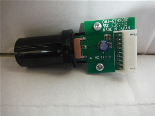
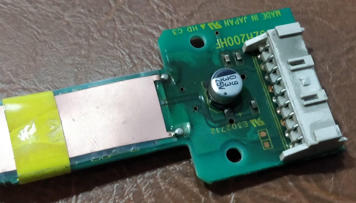
This is the Sega IR Gun sensor (838-14144 / JPT-2030 / OMJ-GZH200D), this has remained mostly unchanged over the years. Notable by the wide PCB with a 9 pin connector do to it’s integration with the trigger switch. Note the large “lip” at the base of the plastic housing, this is how the board mounts inside the gun housing.

This is a Namco Time Crisis 4 Sensor (XTC4-306-754 / OMZ-2D GUN). Note the slimmer PCB shape and the smaller connector due to it not including any pins for the trigger switch. Note the two holes in the center of the PCB, this is how the board mounts inside the gun housing. Also important to note that this board is designed to be mounted parallel to the ground while most other sensors are to be mounted perpendicular to the ground.
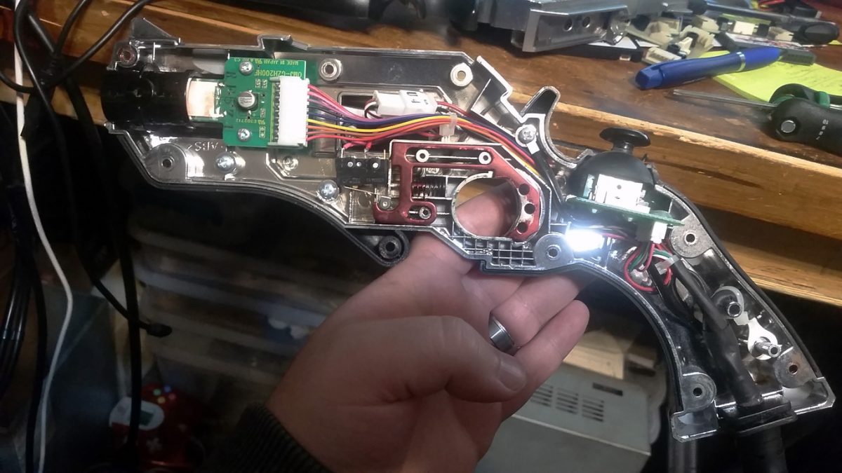
This is the inside of a Taito/Square Enix GunSlinger Stratos Gun. The sensor is nearly identical to the Sega one with the exception of the differently shaped plastic housing. Note the lip in the center of the plastic housing, this is how the board mounts inside the gun housing.

This is a IR Sensor from Namco’s Time Crisis 5. it’s very similar to the Sega Senor module except for the plastic housing. This mounts to the gun housing using the large lip on the end.
There may be other IR Sensor modules in the wild but those above are the ones I know of, If you have photos of others please contact me and I will add them.
Hi, I am trying to hook up the ghost squad arcade gun to my pc using uhid. Can you please help. I have a forum topic here
https://forums.arcade-museum.com/threads/operation-wolf-gun-for-pc.504463/
Can you please put me in touch with the author of this. Thank you, Glenn