In Part 1 I discussed a high level overview of how the Sega/OHMIC IR light gun setup works. Here in Part 2 I’m going to start breaking down the technical details.
As stated in part 1 there are essentially 3 parts to this setup,
1. A chain of 10 or 12 Addressable IR LED boards explicitly positioned around the parameter of the display
2. IR motion sensors in the gun housings.
3. The “Gun Sense” board (essentially the Gun IO).
In this Part I’m going to discuss the LED Boards.
Pinout and Wiring
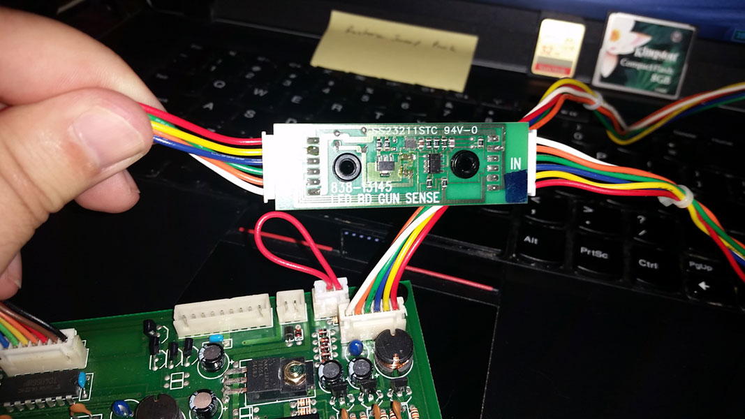
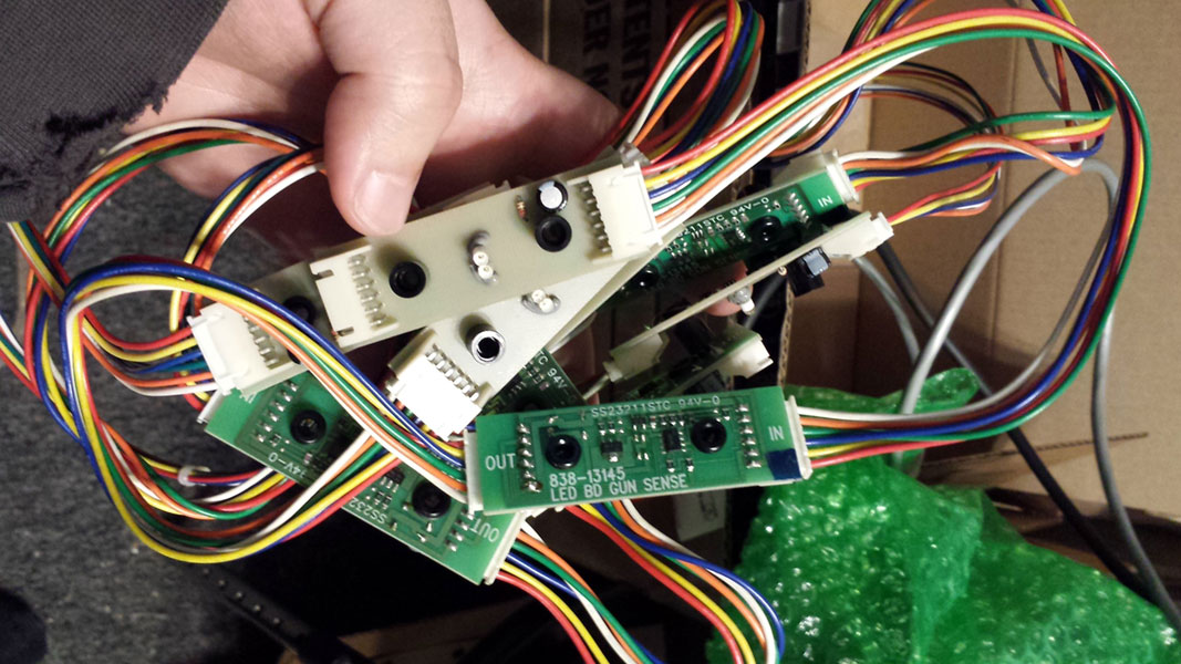
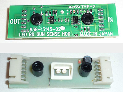
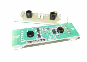
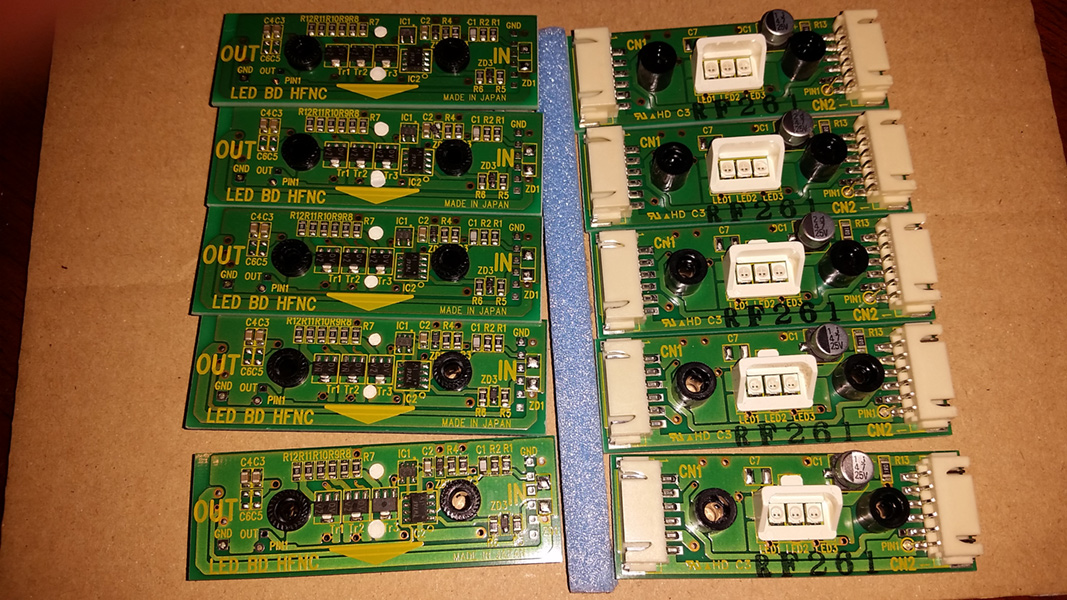
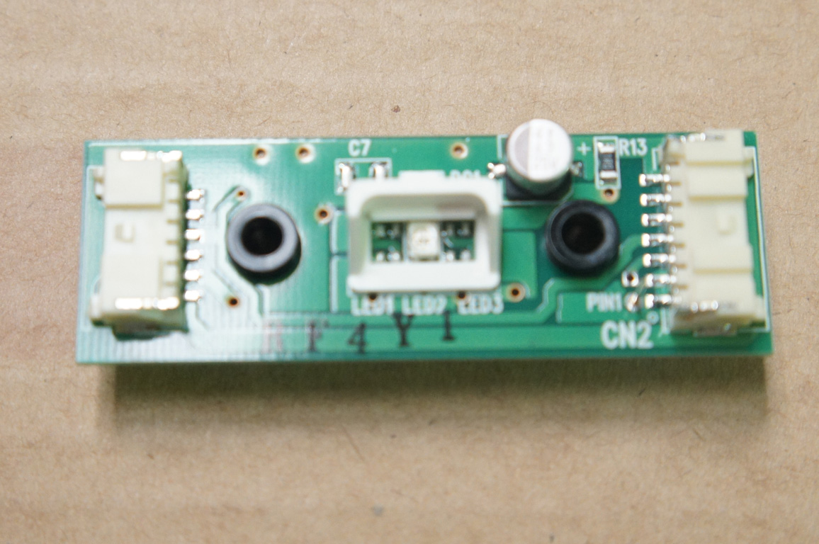
The IR LED modules have two 6-pin connectors. The connectors, one marked “IN” and one marked “OUT”, are pinned identically. The LED modules are designed to be “chained” together with the output of one module going to the input on the next. The input on the first module comes from the Gun Sense board and the output on the last module is left empty; not connected to anything. Interestingly the LED output connector on the gun sense board is pinned backwards from the connectors on the LED modules:

These use a 6-pin JST XH family connector
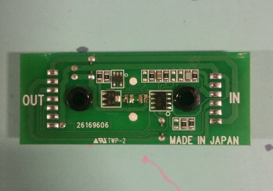
The function of each pin isn’t documented (the manuals simply reference the data pins as “A”, “B”, and “C”) and unless you’re reverse engineering the LED board you simply need to follow the pinning in the picture above. It’s worth noting though that the power pins follow standard Sega wire color. On the LED board connectors the pinout is as follows:
- GND (white)
- A (orange)
- B (green)
- C (blue)
- +5V (yellow)
- +12V (red)
LED Positioning Around the Monitor
Depending on the Gun Sense board, there could be 10 or 12 LEDs in a chain. In-fact Jurassic Park The Lost world was the only game that shipped with 12 LED modules and every subsequent game has used only 10. Despite this fact most of the gun sense boards actually have a dip switch to switch between the 10 and 12 LED configuration (more on this in the Gun Sense Board section).
The 12-LED configuration must be in the pattern below with “1” being the first board in the chain after the gun sense board and “12” being the end of the chain.
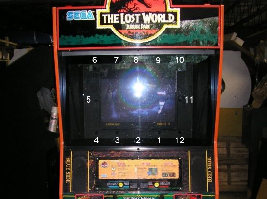
LEDs 4, 6, 10 and 12 are what mark the corners of the screen. Typically these corner LEDs are rotated at a 45degree angle though this is likely for wiring purposes as the angle of the LED board is irrelevant as long as the sensor in the Gun can see it.
The 10-LED configuration must be in the pattern below with “1” being the first board in the chain after the gun sense board and “10” being the end of the chain.
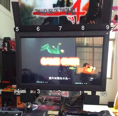
On the 10 LED arrangement you might notice that LEDs 4, 5, 9 and 10 are in the corners and there is no longer any LEDs on the left and right sides of the screen. In both configurations the LEDs should be evenly spaced and aligned parallel with the edge of the screen.
IR Wavelengths
One other thing you might Notice in the photo above is that you can see a faint red light in each of the LED locations. Indeed these IRs LEDs output light that dips slightly into the visible spectrum. It’s enough that in a dimly lit room on close inspection you can easily verify if your LEDs are powering on.
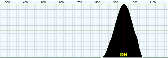
OHMIC supposedly used custom LEDs with a non-standard wavelength to prevent 3rd parties from making and selling replacement parts. I actually tested several of the LED boards against a Light Spectrometer to determine the output range, which you can see below.
Most games came equipped with small Tinted plastic windows that would be placed in front of the LED module. These are designed to let only IR light through so they appear to be a very dark red, almost black in color and they mostly only exist to make the arcade machine look “cleaner”. I’ve found that by NOT using these windows the range in which the guns work can be improved quite a bit.
Troubleshooting
There is not much that can go wrong with the LED boards, they’re pretty robust and the circuit is simple but the LEDs failing is usually what kills them.
Given that you can actually see some faint red light if they’re powering on you can easily tell if the LEDs are dead. Unfortunately due to the proprietary wavelength there are (at the time of this writing) no known good replacements. I do hope to change that eventually once I have some time to test various LEDs on the market and compare their output against the baseline I pulled from the original LED module. Until that happens your only real recourse is to simply replace the whole module. Thankfully replacing only one or two is generally inexpensive.
If you’re wiring up your setup for the first time and some or all of your LEDs aren’t lighting up you’ll want to first verify that it wasn’t installed backwards. Given that the input and output connectors are pinned identical there’s no risk of backwards voltage damaging the board but it also means it’s easy to accidentally install backward. Indeed I’ve done this a few times by accident and it didn’t seem to damage the LED board (at least not after a short period).
LED Board Variations
There are a number of variations of these LED boards, they all seem to be cross-compatible with each other and with any Gun Sense board, you can even mix and match them in the same chain. Though, depending on your cabinet some will work better than others in terms of gun range.
The original 2-LED module used on Jurassic Park The Lost World. Notice that the LEDs are arranged vertically and there is a glob of silicone placed below them to hold them in place. These actually work well with larger screens as you can move and adjust the LED angle to your liking.
This is an LED module from Namco’s Time Crisis 4, it’s nearly identical to the 2 LED Sega Model above. The most notable difference is PCB sizing is slightly different.
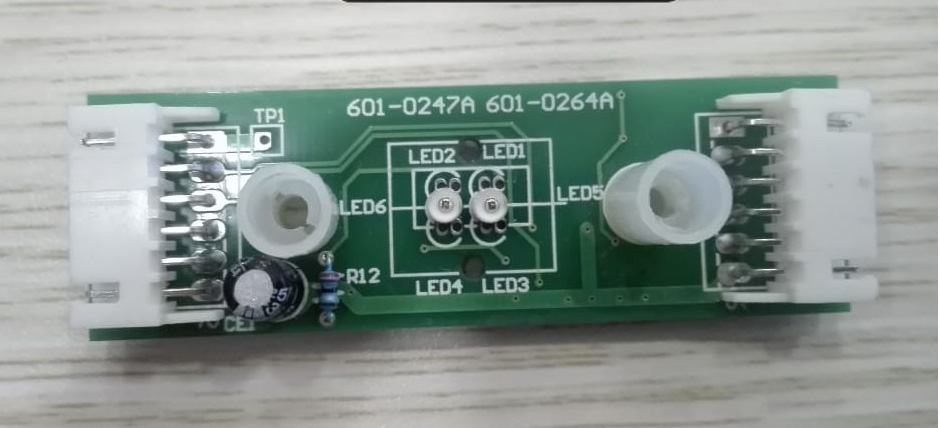
This is an LED module from Namco’s Time Crisis 5, it looks to be the same PCB as the GunSlinger Stratos module but uses different connectors and is only equipped with 1 LED.
There may be other LED modules in the wild but those above are the ones I know of, If you have photos of others please contact me and I will add them.
Really interesting stuff!
Thanks for letting me start to learn this as I hope to do more in the future
But in the meantime.
Do you know of a way to power these LEDs separately? Is the a plug or a way to power via USB?
I have no board for this Rambo unit. It was just the Arcade shell, but the LEDs are still attached to the frame.
Thanks!
You can drive power to them on the connector but it’s a worthless exercise to do so. the Gun Sense board blinks them in a specific pattern for the guns, there’s no benefit to powering them without the Gun Sense board.