I’ve been buried with my work for months now, but it’s a quiet Thanksgiving so I decided to dust off a project. I’ve been rounding out my collection of Rotary stick game so decided to dive into Converting Jackal to the Rotary Stick Version a go.
Some Background
Konami’s Jackal (also known as “Top Gunner” in the USA or “Tokushu Butai Jackal” in Japan) is a top-down Run-and-Gun. The game only ever officially released as a joystick and button game. but the PCB has a 13-pin header like you’d find on SNK Rotary stick games and there is a world region rotary stick dump in MAME, and a few “bootleg” dumps of Rotary stick versions of the game.
ShouTime has this picture online showing a PCB with additional hardware populated: http://collectedit.com/collectors/shou-time-213/arcade-pcbs-281/jackal-world-by-konami-7895
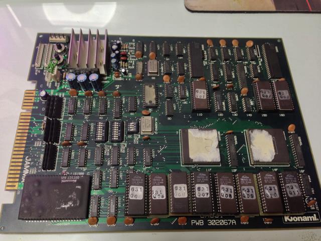
you’ll notice that it’s the exact same PCB number Silk-screening as the normal Production Joystick version:
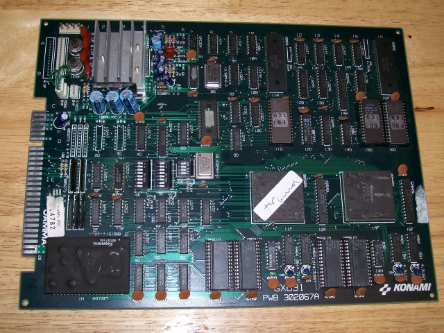
At first glance it looks like there is significant differences with the ROMs on the bottom edge of the board, however you’ll notice on the Rotary stick version there are actually sub-board plugged into the ROM sockets, most likely to help split the larger ROM images into into smaller programmable EPROMs instead of the larger mask ROMs. Note the tan color of the sub-board around the parameter of the ROMs and the GX### silkscreen being obscured by these sub-boards.
So, we’ve already got ROMs for the rotary stick version, and we have confirmation that the PCB is the same so lets see what else is different.
Header Confusion
You’ll notice above on the Joystick version one of the 2 13-pin headers is populated. that’s because the last 4 pins of the header are used as a stereo audio out port, as described in the Operators Manual on page 4.
https://www.gamesdatabase.org/Media/SYSTEM/Arcade//Manual/formated/Jackal_-1986-_Konami.pdf
You can actually see some chunky traces between the Audio section and the pins on the right.
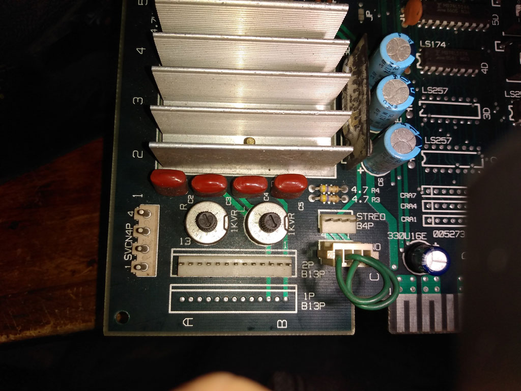
Even though the manual only references the last 4 pins of the “P2” connector you can see on the PCB that the P1 connector is ALSO wired for audio for some reason <_< that’s a damn shame. A Multimeter confirms that the last 4 pins are indeed the same between the two connectors. Further the Ground pins of that audio connection (which wouldn’t be ground on a Rotary stick connector) don’t have visible traces meaning that it would be impossible to cut those traces and add additional wire routes.
This is problematic because if this was truly a header for an LS-30 rotary stick then these last 4 pins would be control inputs, not audio. This seemingly would contradict the PCB being the same between the Rotary version and the production version, And i you look closely on the Rotary version PCB you can see that these chunky Audio traces are present between the P2 and P1 connectors. So how was this accomplished on the “official” rotary stick version of the board?
I decided to start mapping out the other pins to see if it provided any clues.
Missing Parts
There really aren’t a whole lot of missing parts on the joystick version to make it look like the rotary version. Konami was even nice enough to label each of the missing chips with the chip model so we know exactly what to put where. Here’s what’s missing:
- 1P – B13P : JST NH 13 Position Header
- CRA1 – Konami 005273 : Custom Capacitor and Resistor Array
- CRA2 – Konami 005273 : Custom Capacitor and Resistor Array
- CRA4 – Konami 005273 : Custom Capacitor and Resistor Array
- CRA7 – Konami 005273 : Custom Capacitor and Resistor Array
- 2D – LS257 : Quadruple 2-Line To 1-Line Data Selectors/Multiplexers With 3-State Outputs
- 3D – LS257 : Quadruple 2-Line To 1-Line Data Selectors/Multiplexers With 3-State Outputs
- 2D (cap) – 104Z : 0.1uF ceramic Capacitor
- 3D (cap) – 104Z : 0.1uF ceramic Capacitor
The Konami Custom Capacitor and Resistor arrays are thankfully documented so you can build your own, and there are several people that make Repos of these for reasonable prices. It seems to be a fairly common network for handling control inputs. Everything else is off-the-shelf part that is easily sourced.
Connector routing
Looking at the bottom of the PCB most of the non-audio pins on the 13-pin headers are routed to the unpopulated CRA# components.
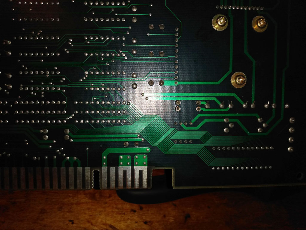
This makes perfect sense since all of the Joystick and button inputs on the JAMMA Edge are routed to CRA# customs that ARE populated. My Hope is that if I start documenting the pins that ARE populated it will give me clues as to how to route the Audio pins where they belong in the input circuit.
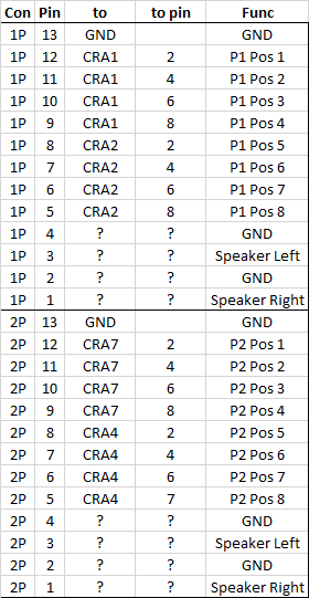
This was further perplexing. As you can see each CRA# custom supports 4 inputs, there are 4 chips depopulated but that’s only 16 inputs across the P1 and P2 rotary ports, to support all 12 input positions two more CRA customs would be needed… but there aren’t any more, not even on the Rotary Stick version of the PCB… what gives?!
At this point I was starting to suspect that the official rotary stick version of this game did NOT in-fact support LS-30 Rotary joysticks, Despite the 13-pin connector the PCB simply didn’t have enough input pins for it. LS-30 joysticks actually have 12-positions when rotating (like the hours on a clock). That’s why the connector has 13 pins, one for ground and then one pin for each position. Spinning the stick simply connects ground to the next position on the clock.
Looking for clues in MAME
Looking in MAME source I found this line describing the inputs for the official World version of the Rotary stick game:
https://github.com/mamedev/mame/blob/master/src/mame/konami/jackal.cpp
    PORT_START("DIAL0") // player 1 8-way rotary control - converted in rotary_r()
    PORT_BIT( 0xff, 0x00, IPT_POSITIONAL ) PORT_POSITIONS(8) PORT_WRAPS PORT_SENSITIVITY(15) PORT_KEYDELTA(1) PORT_CODE_DEC(KEYCODE_Z) PORT_CODE_INC(KEYCODE_X) PORT_FULL_TURN_COUNT(8)
    PORT_START("DIAL1") // player 2 8-way rotary control - converted in rotary_r()
    PORT_BIT( 0xff, 0x00, IPT_POSITIONAL ) PORT_POSITIONS(8) PORT_WRAPS PORT_SENSITIVITY(15) PORT_KEYDELTA(1) PORT_CODE_DEC(KEYCODE_N) PORT_CODE_INC(KEYCODE_M) PORT_PLAYER(2) PORT_FULL_TURN_COUNT(8)
Note that the “PORT_POSITIONS” and “PORT_FULL_TURN_COUNT” are both set at “8”, this matches with what I was seeing on the actual hardware.
Lets sanity check that against an SNK game that we know uses LS-30 joysticks:
https://github.com/mamedev/mame/blob/master/src/mame/snk/snk68.cpp
    PORT_START("ROT1")  /* player 1 12-way rotary control  */
    PORT_BIT( 0x0f, 0x00, IPT_POSITIONAL )  PORT_POSITIONS(12) PORT_WRAPS PORT_SENSITIVITY(5) PORT_KEYDELTA(5) PORT_CODE_DEC(KEYCODE_Z) PORT_CODE_INC(KEYCODE_X) PORT_REVERSE PORT_FULL_TURN_COUNT(12)
    PORT_START("ROT2")  /* player 2 12-way rotary control */
    PORT_BIT( 0x0f, 0x00, IPT_POSITIONAL )  PORT_POSITIONS(12) PORT_WRAPS PORT_SENSITIVITY(5) PORT_KEYDELTA(5) PORT_CODE_DEC(KEYCODE_N) PORT_CODE_INC(KEYCODE_M) PORT_PLAYER(2) PORT_REVERSE PORT_FULL_TURN_COUNT(12)
Note that “PORT_POSITIONS” and “PORT_FULL_TURN_COUNT” are both set at “12”, this is what we’d expect for an LS-30.
Which Stick Does it use?
Well shit. it would seem that the super rare Konami Jackal Rotary stick version doesn’t actually use standard LS-30 style Rotary sticks.. rather it uses some special 8-position version of the sticks. It’s worth noting that the Data East Rotary Sticks are also 12-position and work exactly the same as the SNK LS-30 sticks…
This doesn’t seem to mach with any other rotary sticks I know of …
The “Loop-24” Rotary Sticks used by Caliber .50 and TouchDown Fever are a completely different technology, they work like spinners and only have 4 pins
The Taito Frontline Rotary control isn’t a joystick but more like a rotating button (think a cross between a rotary stick and a Forgotten Worlds Spinner), it has 8 positions but only has 4 wires with the diagonals activating 2 positions at once, like an 8-way jostick… this doesn’t mesh with Jackal’s control either.
With that said I’ve never seen a Rotary stick on any other arcade game that works the way the Jackal inputs are setup to function.
this would have to be something SIMILAR to an LS-30 but with a different circuit board on the bottom.
What would happen if you tried to use an LS-30?
So if we’ve got a 13-pin header and an LS-30 plugs into a 13-pin header, what would happen if you just tried it? Well, it would work normally for 8 of the 12 positions, but then you’d have a 4 position “Dead zone” where it wouldn’t register your position, the game would essentially see no position reported from the stick, as if it was unplugged for those 4 positions. it’s unclear how the game would react to that. Also 2 of those 4 positions are audio outputs that would get grounded through the joystick when they’re selected. This could cause a short and cause the board to reset or worse, burn something up. This could be avoided by removing the caps that are connected to these pins on the connector, but it doesn’t solve the dead-zone problem.
Alternatives?
If you wanted to play this game with a rotary stick you have a few things you could try.
- find a 8-position dial that mechanically connects to an LS-30 and build a custom stick.
- design a daughter-board with a simple logic circuit to translate the 12 position input from an LS-30 to the 8-position inputs that the game expects. You could probably design this to plug right into the 13 pin headers, though you’d also need an additional 5V wire going to the board to power the logic chips.
- design a daughter-board to work with spinner style input from a Loop-24 or traditional spinner. This could also be build to plug right into the headers and would also need an additional 5V wire but the circuit would be a lot more complicated, and you might have trouble tuning the scale of the input to what feels comfortable in-game.
I would think option 2 is the best as it would allow you to use the same rotary joysticks as most other rotary stick games and would have the simplest circuit out of all the options.
I may try my hand at designing such an adapter board but for now I’m satisfied with my new understanding of how the rotary stick version of this game works.
0 Responses to “Konami’s Jackal Rotary Stick Version”