I’ve been playing around with a non-rhythm game version of the Konami System 573 hardware, namely I’m interested in the various “Champ” games, these are collections of manic versus mini-games where you smack buttons and hilarity ensues. The most popular is Hyper Bishi Bashi Champ and Salary Man Champ. If you’re unfamiliar with the game each player has just 3 colored buttons (no joystick) and the buttons also light up corresponding to what’s happening in game.
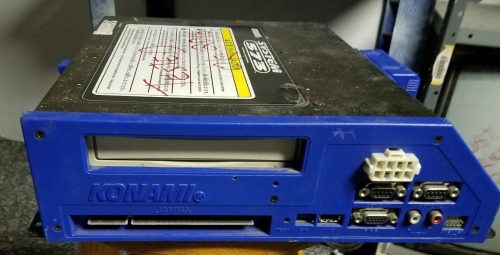
The System 573 hardware has games on disc in addition to a security cartridge. for IO it has both standard JVS connections in addition to a standard JAMMA edge (interestingly player 1 buttons are mapped to player 1 buttons, but player 2’s buttons, including start, are mapped to player 1 joystick) but for light output it’s routed through a connector on the security cart.
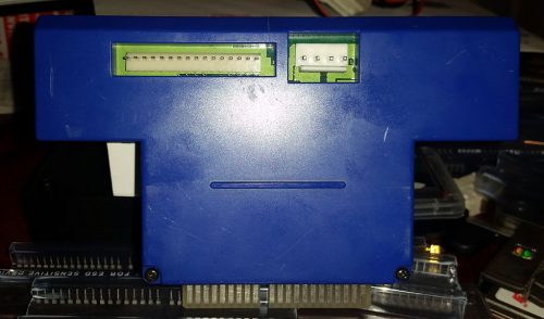
Hooking up lights isn’t completely straight forward. The larger 4 pin header on the right is a power input connector. rather than powering the lights through the edge connector on the security cart an original setup includes a little power harness that taps 12V from the JVS power connector on the front of the system and routes it into the 4 pin connector on the side of the cart with the following pinout:
power input connector
1: GND
2: GND
3: +12V
4: +12V
The larger 16 pin JST NH connector is for the light output and is pinned as follows:
light output connector:
1: P1 B1 Lamp
2: P1 B2 Lamp
3: P1 B3 Lamp
4: +12V
5: N/C
6: N/C
7: N/C
8: N/C
9: P2 B1 Lamp
10: P2 B2 Lamp
11: P2 B3 Lamp
12: +12V
13: N/C
14: N/C
15: N/C
16: N/C
Outputs without a security cartridge
There are some bootlegs out there that use a security cart reprogrammed from another game, as well as some that don’t even use a security cart at all. I have a friend who is interested in getting light output working on his setup which does not include a security cart at all. So I decided to crack open the cart and see if I could reverse engineer the light output from the edge connector.
Here are the insides of my Salary Man Champ cartridge:

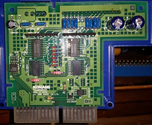
looking at the insides you’ll notice a small chip on the left and an even smaller on on the bottom right. These are the actual security chips, nearly everything else in here is for the light output; but it’s not as complicated as it seems.
On the solder-side of the PCB you’ll notice pins 13, 14 and 15 have thin traces connected to them, these three pins alone control the light output. they’re routed to the 2 16-pin SMD chips in the center of the cart, which are both 74HC4094 shift-registers. the outputs from those shift registers are fed into some transistors (by way of the Mitsubishi SMDs directly above each of the 4094s) and on their way to the output pins, of course there are also some filters, caps, resistors and diodes there to help with the signal as well.
I’m not entirely sure 2 of those 4094s are needed as they seem to be chained but only utilize half of each chip. Also, while this game only has 6 light outputs there are provisions for 8 lamps on this PCB all one would need to do is add in the 2 missing filters and diodes to complete the circuit for those lamps (though I’m unclear if the game ever illuminates these).
In any case if one wanted to duplicate this circuit for the sake of lamp output you’d need to get 2x 74HC4094 chips and wire them as follows:
LEFT 74hc4094
1 – edge pin 14
2 – right 74hc4094 pin 10
3 – edge pin 15
4 – output header pin 4 (unpopulated)
5 – output header pin 3
6 – output header pin 2
7 – output header pin 1
8 – GND
15- +5V
16- +5V
RIGHT 74hc4094
1 – edge pin 14
2 – edge pin 13
3 – edge pin 15
7 – output header pin 11
8 – GND
10- left 74hc4094 pin 2
11- output header pin 5 (unpopulated)
13- output header pin 9
14- output header pin 10
15- +5V
16- +5V
I’m unsure of the actual edge pin numbering so the numbers above are counted from left to right on the solder-side of the security cart (the side the faces away from the main PCB) and counts the slot as a pin. It should also go without saying but you shouldn’t simply output directly to the header, all outputs should be run through a transistor that is strong enough to drive your lamps in addition to a pull-up resistor.
For reference on the solder-side of the cart the first three pins are ground and the last two pins (21 and 22) are +5V. These will obviously be necessary for powering the 4094 chips.
I haven’t tested the above, so if you do please report back with how it worked out. Also please see if you can get away with using only 1 4094 I’d be interested to see if all 8 outputs could be working on 1 chip.
JVS Output
where this is a JVS compliant PCB it’s also possible that you could simply get light output from a JVS IO. I haven’t had a chance to test this but it’s entirely possible that JVS outputs are not enabled despite them being available on the hardware. If I do ever get around to testing it I’ll make and update here. Or if you have any experience with JVS on these “champ” games let me know if light output (or even user input) work over JVS.
UPDATE #1
I didn’t have any 4094 ICs but I did have some 595 shift registers. I was able to chain 2 together and solder to the correct pins on a Fisherman’s Bait Cart and get working lights through that.
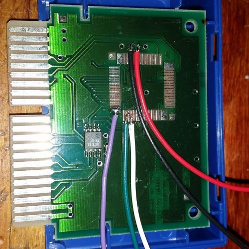
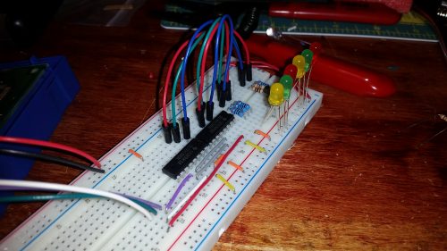
Any 16-position shift register should work. the lights are arranged within the register like this:
0 – N/A
1 – N/A
2 – N/A
3 – P2 B3
4 – P2 B2
5 – P2 B1
6 – N/A
7 – N/A
8 – P1 B1
9 – P1 B2
10- P1 B3
11- N/A
12- N/A
13- N/A
14- N/A
15- N/A
I’ve also discovered that this only works for Salary Man Champ. Hyper Bishi Bashi Champ uses a completely different circuit for light output. If I can get my hands on a HBBC cart I’ll make a new entry with how that one works.
0 Responses to “Light output for Salary Man Champ on Konami System 573”