Ever since I saw the WiiFree LCD mod I’ve been racking my brain how to integrate an LCD into such a small case and the key to it all came to me one weekend, after which I went straight online and ordered everything I needed.
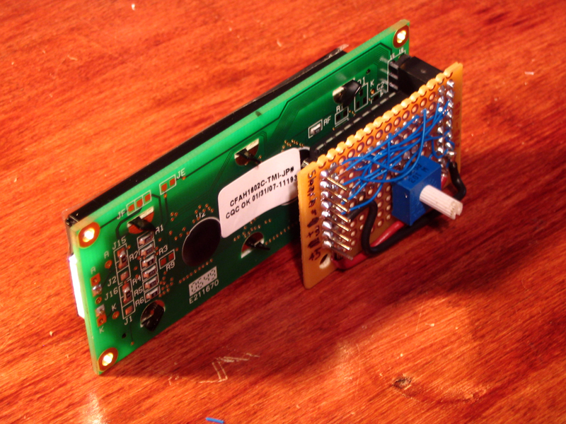
I originally wanted to use a RED 20×2 I had laying around but it wouldn’t fit how I wanted it. I have a 16×2 green VFD I could have used but it would require some tinted glass so I didn’t want to use that. I ordered two White on blue 16×2 LCDs from CrystalFontz which will mesh perfectly with the Wii’s natural styling.
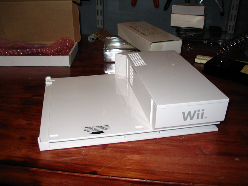
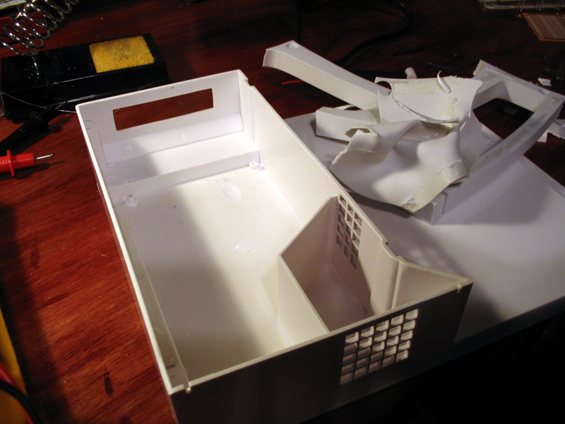
I had been racking my brain trying to figure out how to fit an LCD into the Wii’s case because of how incredibly small it is and how tight the innards are. While I was poking around Circuit City I saw an interesting product, a horizontal stand for the Wii with a matching box off to the site designed to hold a remote and nunchuck. As you can see from these pictures the potential for a slick LCD add-on is great.
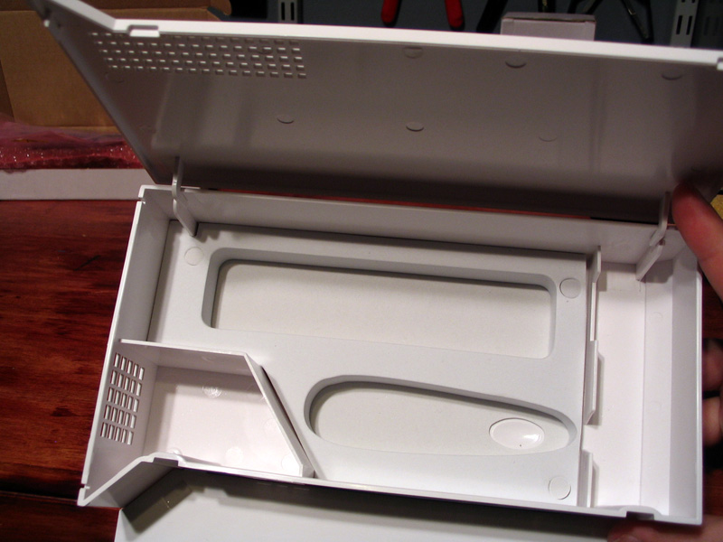
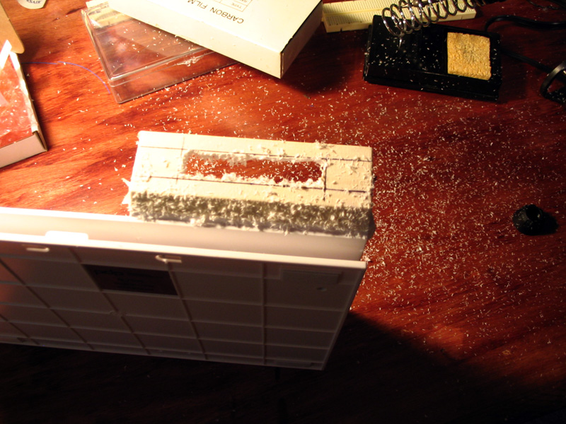
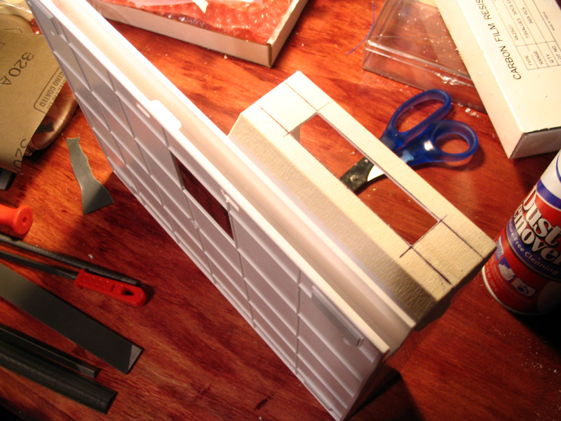
I started by measuring my LCD to get the dimensions of the viewable area, and playing with placement to make sure that it would fit inside the case with the lid closed and still look centered on the outside. Even with all the empty space here the height of the case and the angled bottom still made this a tight fit that required a little bit of trimming. Once I got the placement down I masked off where I was going to cut my window. Used a rotary tool to rough cut it and then used metal files to make the cuts clean and flat and then finally some light sanding on the edges to make them look natural and slightly rounded. I did it this way because I didn’t want to have to paint the case the glossy plastic of the stand matched the Wii perfectly and having to paint or bondo to cover up any mistakes would have ruined that perfect match.

Once the cuts were made I gutted the interior to remove all of the crap that I don’t need. While I don’t need the empty space either I figure that it might be beneficial for future projects, it might be cool to hardwire a set of Wavebird wireless adapters in here or hardwire a USB port and a LAN adapter or something along those lines. There’s certainly enough space for all of those things.
Now that the case was done I could turn to the electronics. I knew that I needed a small PCB and I wanted it to sit like a backpack on the back of the LCD. I wanted to mount the chip to the back of the LCD rather than inside the Wii because if I ever need to reflash it getting at the chip would be trivial. Using pin headers to connect everything meant that I could easily pull the system apart for repairs or adding features down the road. I started by laying out how the electronics would all fit on a PCB, then I soldered them in place, then I went pin by pin from the WiiFree install instructions to make sure all of the points on the chip lined up with all of the points on my custom pin header. It was a lot easier than it looks. One benefit to using a socket for the chip is that you can solder it in place with the chip removed, meaning you don’t risk damaging the chip with the heat of the iron.

Once I had the electronics all soldered up I could place the LCD inside the case to complete the look. The LCD was simply hot glued in place. Using multiple dots of hot glue is the best procedure as even if one drop breaks the whole glue seam wont rip off like a string. Hot glue is fine for situations like this too because it’s not really holding any weight or resisting any force. Not to mention if you screw up it’s pretty easy to remove it and fix it.
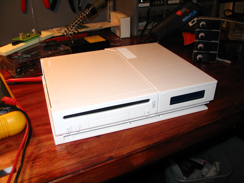
So I have this awesome looking Wii LCD case now. I went ahead and soldered up a ribbon cable internally to a pin header hanging out the back of the case (sorry I forgot to take pictures) and I was all ready to get this thing up and running. Unfortunately when I went to flash the firmware to my chip I came to the painful realization that by USB programmer, a programmer that I bought because it works with 99.9% of Microchip’s PIC products did not support the chip I was using. I would seem that this is one of the very few chips that falls into that .1% range. So without the firmware I had to go back to using my internal 12F629 for the time being. I’ll get around to building a programmer for the chip I’m using to get the LCD up and running but it will have to wait until the next time I put in my big annual Digikey parts order.
You can follow the progress of this project using the project log on Nintendo-Scene.
Nice hack man.
Where exactly did you get the case? I’m thinking of getting myself one (without making it a super computer of course).
I honestly don’t remember, I think it was some cheap $10 accessory I found in the bargain bin at Walmart or GameStop back when the original Wii was still relevant.